HP Vectra Accessory
Service Handbook
5th Edition
HP Part No. 5963-8034
Printed in France December 1995
Fifth Edition (replaces earlier editions)
© 1995 Hewlett-Packard Company

REPLACEABLE PARTS FOR VIDEO BOARDS
Replaceable Parts
Description Replacement
Part Number Exchange
Part Number
Intelligent Controller 20 (A1083A) A1083-66570 A1083-69570
Intelligent Controller 10 Main board (A1086A) A1086-66570 A1086-69570
Memory Extension Board (A1087A) A1087-66576 -
HP EGA Board, 256 KB (45983A) 45983-60001 1150-1784
HP VGA Board (D1180A)
HP Super VGA Board, 256 KB (D2382A) D2382-63004 D2382-69004
256 KB Upgrade Kit (D2383A) 81818-4482 -
HP Ultra VGA Board 512 KB (D2325A/B) D2325-63009 -
VESA compliant BIOS upgrade D2325-60011 -

4 HP HARD DISK AND GENERAL CONTROLLER
BOARDS
OVERVIEW
This chapter provides information about the following HP controller boards:
HP ST-506 Four-Function Controller Board (45945-60013)
HP ESDI Four-Function Controller Board (D1677A)
HP ESDI High Performance Controller Board (D1664A)
HP ISA SCSI-1 Host Adapter Board (D2886-63002) for CD-ROM
HP EISA SCSI-2 Host Adapter Board (D1681A/D2649A)
HP ISA SCSI-2 Host Adapter Board (D1682A)
HP IDE Multifunction Controller Board (D2384-63031)
HP ISA IDE Controller Board for CD-ROM (D2889-63002)
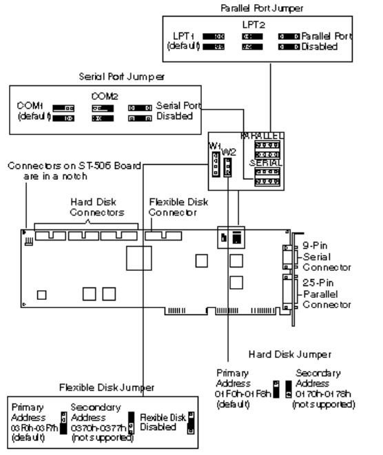
HP ST-506 CONTROLLER BOARD (45945-60013)
AND HP ESDI CONTROLLER BOARD (D1677A)
HP ST-506 and ESDI Board Default Jumper Settings
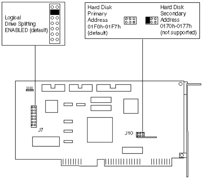
HP ESDI HIGH PERFORMANCE CONTROLLER BOARD (D1664A)
D1664A Default Jumper Settings
The HP D1664A ESDI Controller uses IRQ 14.
You cannot install a second hard disk when logical drive splitting is enabled.
HP ISA SCSI-1 HOST ADAPTER BOARD (D2886-63002) FOR CD-ROM
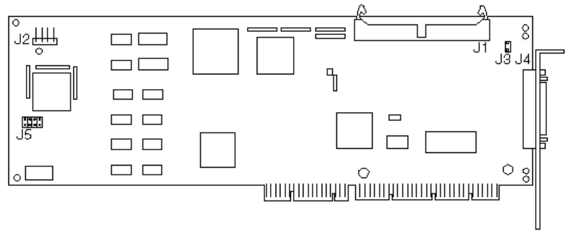
HP EISA SCSI-2 HOST ADAPTER (D1681A/D2649A)
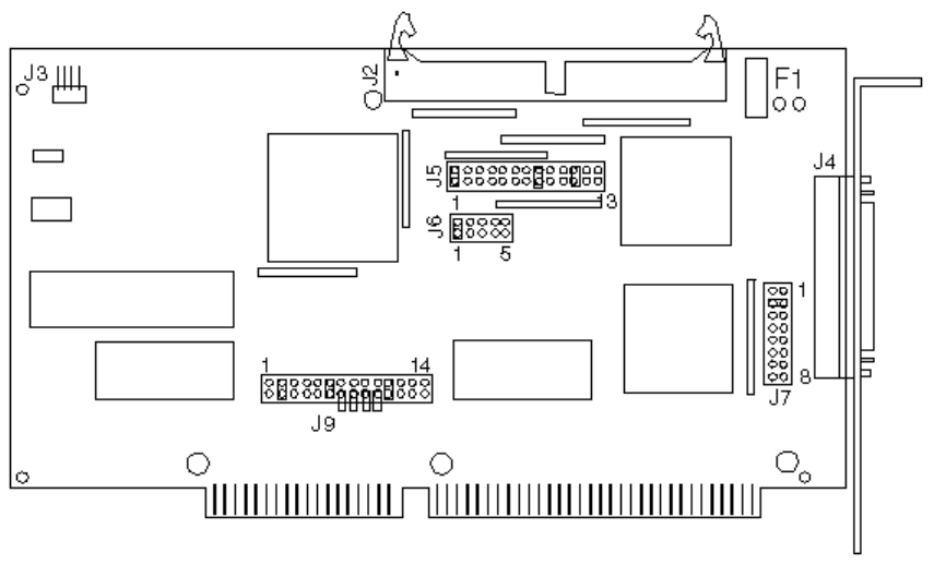
D1681A/D2649A Locations of Connectors and Default Jumper Settings
J1 is the internal SCSI device connector.
J2 is the activity light connector.
J3 is the terminator power jumper (remove to disable terminator power).
J4 is the external SCSI device connector.
J5 is the factory test jumper/connector.
The EISA Configuration file is: !ADP0000.CFG
This board must be configured using the EISA system configuration utility (EASY CONFIG or
SAM, see chapter 7).
The D2649A is the same as the D1681A but includes the HP Vectra 486ST PC’s SCSI
terminated cable.

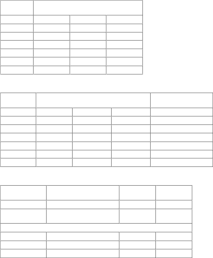
D1681A/D2649A Default Configuration
Computer Resource Standard
Mode Enhanced Mode
If Auto Config. If Manual Config.
DMA Channel 5 N/A* N/A
IRQ Channel 11 11 11
I/O Port Address 330 h N/A N/A
BIOS Address 0C8000 h 0C8000 h 0C8000 h
EISA Bus On Time 4 [micro]s 4 [micro]s 4 [micro]s
SCSI Options
SCSI Address 7 7 7
SCSI Device N/A Installed -
Report Error Not Installed
SCSI Bus Reset at Power
On at Power On at Power On
Synchronous
Negotiation Enabled Enabled Disabled
Bus Parity Enabled Enabled Disabled
Disconnection Enabled Enabled Disabled
Send Start Command N/A Disabled Disabled
Logical Units N/A One One
Max. Synch Xfer Rate N/A 5 MB 5 MB
Bus Terminators Installed Installed Installed
Terminator Power Supplied Supplied Supplied
*Not applicable
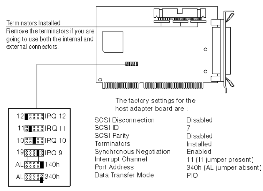
HP ISA SCSI-2 HOST ADAPTER (D1682A)
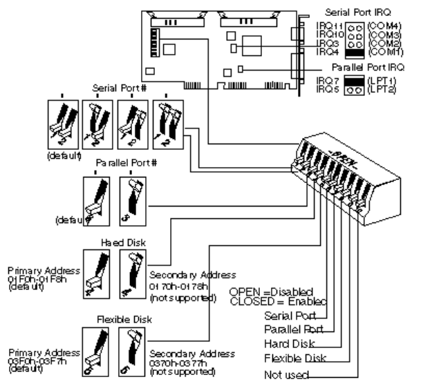
D1682A Default Jumper Settings
D1682A Default Configuration
DMA Channel 5
DMA Transfer Speed 5 MB/s
IRQ Channel 11
I/O port address 330 h
SCSI Address 7
SCSI Parity Enabled
Synchronous Negotiation Enabled
Auto Sense Enabled
The HP ISA SCSI Host Adapter must be set to device address 7. It is the highest priority
address and the only host adapter address supported by Hewlett-Packard.
ALTERNATE D1682A CONFIGURATIONS
I/O Port Address Jumper Settings (default in bold)
I/O Port
Address Jumper 7 (J7)
Position 2 Position 3 Position 4
130 h CLOSED - CLOSED
134 h - - CLOSED
230 h CLOSED CLOSED -
234 h - CLOSED -
330 h CLOSED --
334 h - - -
Interrupt Channel Jumper Settings (default in bold)
Interrupt
Channel Jumper 5 (J5)
Jumper 9 (J9)
Position 9 Position 10 Position 11
IRQ 9 - - -
Position 9 CLOSED
IRQ 10 CLOSED - -
Position 10 CLOSED
IRQ 11 - CLOSED -
Position 11 CLOSED
IRQ 12 CLOSED CLOSED -
Position 12 CLOSED
IRQ 14 - - CLOSED
Position 13 CLOSED
IRQ 15 CLOSED - CLOSED
Position 14 CLOSED
BIOS and DMA Jumper Settings (default in bold)
Configuration Jumper Enabled
(default) Disabled
BIOS Jumper 6 (J6) Position 1 CLOSED -
Synchronous
negotiation Jumper 5 (J5) Position 1 CLOSED -
DMA Channel
Channel 5 Jumper 5 (J5) Position 8 CLOSED -
DREQ Jumper 9 (J9) Position 2 CLOSED -
DACK Jumper 9 (J9) Position 6 CLOSED -
HP IDE CONTROLLER BOARD (D2384-63031)
IDE Controller Board Default Jumper Settings
HP ISA IDE ADAPTER BOARD FOR CD-ROM (D2889-63002)
The ISA IDE controller board D2889-63002 is bundled with the 2x IDE CD-ROM D2889-63001,
in product number D2889A. For information on the CD-ROM, refer to chapter 5, "HP CD-ROM
Devices".
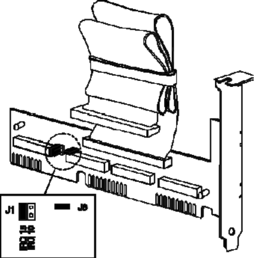
By default, the jumper settings for the D2889-63002 controller board are:
• J1 set to IRQ 15
• J8 set, for I/O address 170h-177h (primary), 376-h-377h (secondary).
Alternative jumper settings are:
• J1 set to IRQ 10
• J8 removed, for I/O address 160h-167h (primary), 16Eh-16Fh (secondary).

REPLACEABLE PARTS FOR HARD DISK AND GENERAL CONTROLLER
BOARDS
Description
Replacement
Part Number
Exchange
Part Number
HP ST-506 Four-Function Controller Board
HP ESDI Four-Function Controller Board (D1677A)
1150-1803
HP ESDI High Performance Controller Board (D1664A)
HP ISA SCSI-1 Host Adapter Board for CD-ROM
(D2886A)
-
HP EISA SCSI-2 Host Adapter Board (D1681A/D2649A)
1150-1920
HP ISA SCSI-2 Host Adapter Board (D1682A)
D1682A SCSI Board Jumpers
1258-0209
-
HP IDE Multifunction Controller Board
Flexible Disk Expander Board
-
Flexible Disk Expander Cable
-

5 HP MASS STORAGE DEVICES
This chapter describes hard disk drives, flexible disk drives and CD-ROM drives. For
replacement part numbers of mass storage devices, refer to "Replacement Part Numbers for
Mass Storage Devices" in this chapter. For information on rails and trays, see chapter 10, Rails
and Trays.
The mass storage devices described in this chapter are listed below.
Discontinued devices
are
in
italics
.
Part Number
Description Page
Flexible Disk Drives:
1.2 MB flexible disk drive 5-10
1.44 MB flexible disk drive in 5.25-in tray 5-12
D2035A/B
1.44 MB flexible disk drive 5-12
1.2 MB flexible disk drive 5-10
D2881A/B
1.2 MB flexible disk drive 5-11
CD-ROM Drives:
IDE 2× CD-ROM drive and IDE adapter board 5-13
IDE 4× CD-ROM drive 5-14
IDE 4× CD-ROM drive 5-15
D2886A/B
SCSI CD-ROM drive and SCSI adapter board 5-17
ST-506 Hard Disk Drives:
20 MB ST-225 hard disk drive 5-19
40 MB ST-251hard disk drive 5-19
EDSI Hard Disk Drives:
108 MB EDSI hard disk drive 5-19
152 MB EDSI hard disk drive 5-19
330 MB EDSI hard disk drive 5-20
670 MB EDSI hard disk drive 5-20
103 MB EDSI hard disk drive 5-20
155 MB EDSI hard disk drive 5-20
310 MB EDSI hard disk drive 5-20

Part Number
Description Page
IDE Hard Disk Drives:
42 MB IDE hard disk drive 5-22
84 MB IDE hard disk drive 5-22
120 MB IDE hard disk drive 5-22
168 MB IDE hard disk drive 5-22
dual-168 MB IDE hard disk drive 5-23
52 MB IDE hard disk drive 5-24
120 MB IDE hard disk drive 5-24
240 MB IDE hard disk drive 5-24
240MB IDE hard disk drive 5-24
85 MB IDE hard disk drive 5-24
170 MB IDE hard disk drive 5-24
D2328-6000x
40 MB IDE hard disk drive 5-24
170 MB IDE hard disk drive 5-27
210 MB IDE hard disk drive 5-27
D2387-60101
210 MB Fast IDE hard disk drive 5-28
270 MB IDE hard disk drive 5-30
540 MB IDE hard disk drive 5-30
D2390A
270 MB IDE hard disk drive 5-27
D2391A
540 MB IDE hard disk drive 5-27
D2392-6xxxx
420 MB IDE hard disk drive 5-29
D2393-6xxxx
840 MB IDE hard disk drive 5-29
D2394-6xxxx
360 MB IDE hard disk drive 5-32
D2395-6xxxx
540 MB IDE hard disk drive 5-32
D2396-6xxxx
720 MB IDE hard disk drive 5-32
450 MB IDE hard disk drive 5-26
340 MB IDE hard disk drive 5-27
D2890-60101
340 MB Fast IDE hard disk drive 5-28
D2891A/B
540 MB IDE hard disk drive 5-27
D2894A/B
270 MB IDE hard disk drive 5-27
D2906-6xxxx
420 MB IDE hard disk drive 5-28
D2916-6xxxx
420 MB IDE hard disk drive 5-34
540 MB IDE hard disk drive 5-34
1 GB IDE hard disk drive 5-34
840 MB IDE hard disk drive 5-34
D2927-6xxxx
1.6 GB IDE hard disk drive 5-29
D2928-6xxxx
2 GB IDE hard disk drive 5-35
630 MB IDE hard disk drive 5-34
1.2 GB IDE hard disk drive 5-34
D2939-6xxxx
630 MB IDE hard disk drive 5-28
D3032-6xxxx
106 MB IDE hard disk drive 5-24

Part Number
Description Page
SCSI Hard Disk Drives:
440 MB SCSI hard disk drive 5-37
670 MB SCSI hard disk drive 5-39
1 GB SCSI hard disk drive 5-39
430 MB SCSI hard disk drive 5-41
430 MB SCSI hard disk drive 5-41
535 MB Fast SCSI-2 hard disk drive 5-43
D2076A/B
1053 MB Fast SCSI-2 hard disk drive 5-43
270 MB SCSI-2 hard disk drive 5-45
540 MB SCSI-2 hard disk drive 5-45
D2398-6xxxx
540 MB SCSI-2 hard disk drive 5-46
1 GB SCSI hard disk drive 5-42
1 GB SCSI hard disk drive 5-42
D2904-6xxxx
1 GB SCSI-2 hard disk drive 5-47
1 GB SCSI-2 hard disk drive 5-49
2 GB SCSI-2 hard disk drive 5-51
HARD DISK DRIVE CONTROLLERS
Flexible Disk Drives
Product Disk Drive Controller
5.25-inch, 1.2 MB
3.5-inch, h-h, 1.44 MB
Any (apart
from D1664A)
D2035A/B
D2881A/B
3.5-inch, low-profile, 1.44 MB
5.25-inch, h-h, 1.2 MB
5.25-inch, h-h, 1.2 MB
Integrated
flexible disk
drive
controller
CD-ROM Drives
Product Disk Drive Controller
controller*
*Drives supported only on PCs with integrated IDE controller (except on 486T).
MFM (ST-506) Hard Disk Drives
Product Disk Drive Type Controller
ESDI Hard Disk Drives
Product Disk Drive Type Controller
IDE Hard Disk Drives
Product Disk Drive Type Controller
63031
1
*D1665A/6A and D1679A/80A use integrated IDE controller on Vectra 486T PCs.

The IDE hard disk drives not listed above use the integrated IDE controller. These IDE hard disk
drives are supported only on PCs with an integrated IDE controller (except on the 486T).
SCSI Hard Disk Drives
Product Disk Drive
Controller
D1681A or D1682A

HARD DISK BIOS COMPATIBILITY MATRIX
VECTRAS IN THE CLASSIC DESKTOP BOX
All Vectras in the low-profile, the medium-profile, and full-height boxes have automatic hard
disk detection in BIOS. All supported hard disks are recognized, regardless of BIOS version.
Vectra QS PC Minimum ROM BIOS Version
HP Disk QS/16 ROM BIOS QS/16S ROM BIOS QS/20 ROM BIOS
D1296A, 20 MB type 2 D.02.00 (Jun 29, 88) F.02.00 (Mar 29, 89) D.02.01 (Feb 1, 89)
D1297A, 40 MB type 44
D1445A, 108 MB type 40
D1446A, 152 MB type 41
D1665A, 42 MB type 37
D1666A, 84 MB type 38
D.02.07 (Aug, 93)
Support parts only F.02.03 (Nov 20, 89) D.02.03 (Oct 30, 89)
D1679A, 120 MB type 10 F.02.04 (Jun 22, 90) D.02.04 (Jun 22, 90)
D1680A, 168 MB type 13
Vectra 286/12 PC Minimum ROM BIOS Version
HP Disk ROM BIOS
D1296A, 20 MB type 2 H.03.01 (Mar 29, 90)
D1665A, 42 MB type 37
D1666A, 84 MB type 38
Vectra 386/25 PC Minimum ROM BIOS Version
HP Disk ROM BIOS
D1665A, 42 MB type 37 J.03.00 (May 11, 90)
D1666A, 84 MB type 38
D1679A, 120 MB type 10
D1680A, 168 MB type 13
D1688A, 2x68 MB
VECTRAS IN THE DESKSIDE BOX
Vectra RS PC Minimum ROM BIOS Version
HP Disk RS/16
ROM BIOS RS/20
ROM BIOS RS/20C
ROM BIOS
RS/25C
ROM BIOS
D1297A, 40 MB type 44 C.02.01 (Mar 25, 88) E.02.00 (Dec 7, 88)
D1674A, 103 MB type 45
D1675A, 155 MB type 46
D1676A, 310 MB type 47
D1660A, 330 MB type 27
D1661A, 670 MB type 30
Not supported E.02.02 (Oct 30, 89)
D1665A, 42 MB type 37
D1666A, 84 MB type 38
D1679A, 120 MB type 10
D1680A, 168 MB type 13
Not supported
E.02.03
(June 22, 90)
Vectra 486T Minimum ROM BIOS Version
HP Disk 486
ROM BIOS 486/25T
ROM BIOS
486/33T
ROM BIOS
D1445A, 108 MB type 40
D1446A, 152 MB type 44
G.03.01 (Feb 5, 90)
K.03.01
(Feb 7, 91)
D1660A, 330 MB type 27
D1661A, 670 MB type 30
D1665A, 42 MB type 37
D1666A, 84 MB type 38
D1679A, 120 MB type 10 G.03.02 (June 22, 90)
D1680A, 168 MB type 13
D1685A, 440 MB
D1686A, 670 MB
D1687A, 1000 MB
Vectra 486ST PC Minimum ROM BIOS Version
HP Disk ROM BIOS
D2643A, 240 MB R.01.00 (June 92)
D2644A, 430 MB
D2645A, 1000 MB
D2653A, 1000 MB
Flexible Disk Information:
1. If the computer has a tape drive, ensure its jumpers are correctly set to avoid flexible disk
drive errors (for example “general read error”).
2. If the computer has three or more flexible disk drives, install the DRIVER.SYS driver.
3. The pin 1 wire on the disk drive cable is usually color-coded.
4. On flexible disk drive cables that have a twist, the connector after the twist must be
connected to the first flexible disk drive A.
Hard Disk Initialization Information:
1. ST-255 20 MB and ST-251 40 MB hard disk drives must be initialized using option #4 of
the Setup Program.
2. All ESDI and IDE and SCSI hard disk disks are delivered pre-initialized. IDE disk drives
must NOT be re-initialized.
3. If a second hard disk is installed, you may need to run FDISK before it is recognized.
4. If an IDE drive is installed in a system with previously installed SCSI drive, it becomes the
bootable drive.
In this case,
before
installing an IDE hard disk drive, make bootable copies of the
operating system. Refer to the operating system documentation for information on how to
create a bootable diskette, formatting a drive, and installing the operating system.

HP FLEXIBLE DISK DRIVES
This section describes the following flexible disk drives:
Part Number
Description Page
1.2 MB flexible disk drive 5-10
1.44 MB flexible disk drive in 5.25-in tray 5-12
D2035A/B
1.44 MB flexible disk drive 5-12
1.2 MB flexible disk drive 5-10
D2881A/B
1.2 MB flexible disk drive 5-11
HP 45812A 5.25-INCH 1.2 MB AND
HP D2036A 5.25-INCH 1.2 MB FLEXIBLE DISK DRIVES
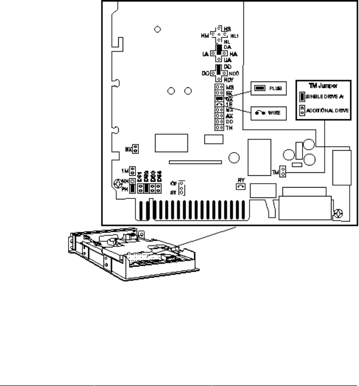
1.2 MB Disk Drive Default Jumper Settings
The default setting for the “TM” (termination resistor) jumper is:
• set if the disk was bundled as the only 5.25-inch drive
• not set if the disk was purchased as a separate accessory
If the drive is in: Set the TM jumper to:
A:
B:
E:
F:
Set
NOT set
Set
NOT set
The TM jumper is ignored if
there is a 3.5-inch flexible disk
drive in A:
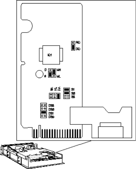
HP D2881A 5.25-INCH 1.2 MB FLEXIBLE DISK DRIVE
1.2 MB Disk Drive Default Jumper Settings
D2881B is produced in grey instead of beige.
HP D1667A 3.5-INCH 1.44 MB AND
HP D2035A/B 3.5-INCH 1.44 MB FLEXIBLE DISK DRIVES
ISA Configuration (default setting)
EISA Configuration
3-Mode Configuration (Japan)
Jumper Settings for
support parts
D2035-63021 and D2035-63121
HP D2035B Flexible Disk Drive
The new color is grey, instead of beige, and jumpers are no longer required.
EISA PCs include the 486S, 486T, 486ST, and 486U PC series.
HP CD-ROM DRIVES
This section describes the following CD-ROM drives:
Part Number
Description Page
IDE 2× CD-ROM drive and IDE adapter board 5-13
IDE 4× CD-ROM drive 5-14
IDE 4× CD-ROM drive 5-15
D2886A/B
SCSI CD-ROM drive and SCSI adapter board 5-17
HP D2889A IDE 2× CD-ROM AND ADAPTER BOARD
The 2× IDE CD-ROM (D2889-63001) is bundled with the ISA IDE adapter board (D2889-
63002). For information on the adapter board, refer to page 4-10.
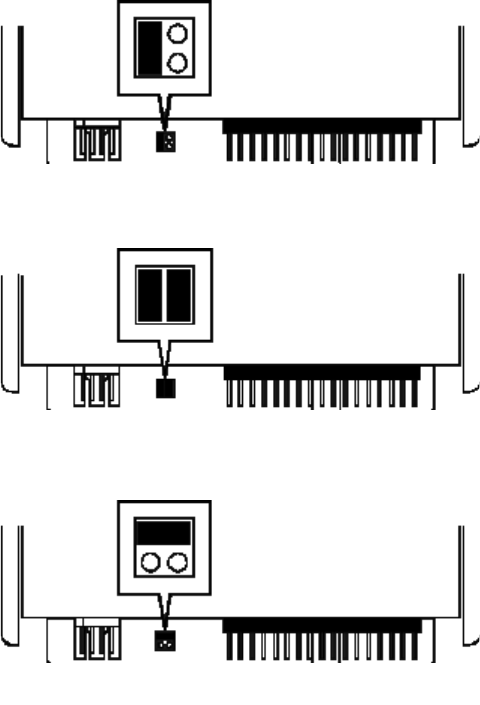
The D2889-63001 has three jumper settings: CSEL, SLAVE and MASTER.
If the CD-ROM is the only drive connected to an IDE data cable, set the jumper to MASTER. If
the CD-ROM is connected to the secondary connector on the IDE hard disk drive data cable,
set the jumper to SLAVE.
D2896A IDE 4× CD-ROM DRIVE
Description Service Part Number
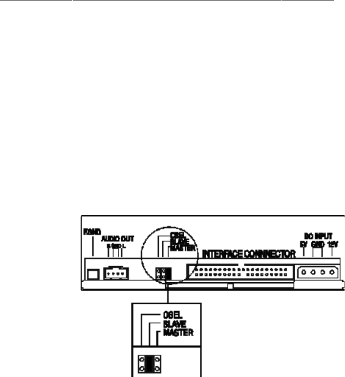
The D2896A has three jumper settings: CSEL, SLAVE and MASTER.
If the CD-ROM is the only drive connected to an IDE data cable, set the jumper to MASTER. If the
CD-ROM is connected to the secondary connector on the IDE hard disk drive data cable, set the
jumper to SLAVE.
D2896B IDE 4× CD-ROM DRIVE
Description Service Part Number
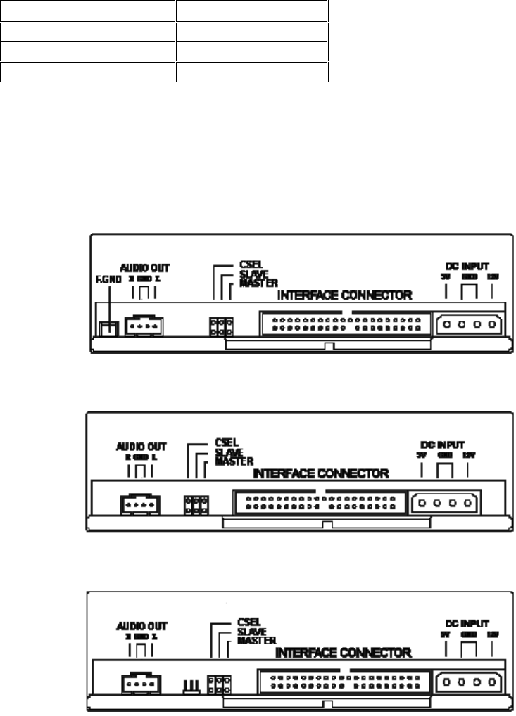
The D2896B has three jumper settings: CSEL, SLAVE and MASTER.
If the CD-ROM is the only drive connected to an IDE data cable, set the jumper to MASTER. If
the CD-ROM is connected to the secondary connector on the IDE hard disk drive data cable,
set the jumper to SLAVE.
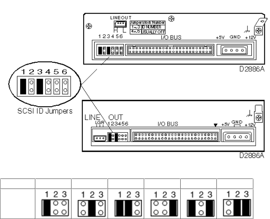
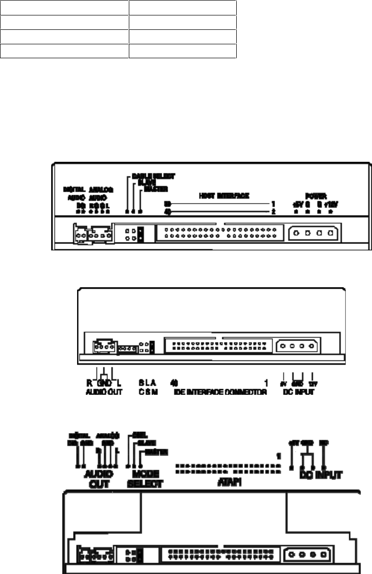
HP D2886A/B SCSI CD-ROM DRIVE
If you are using the CD-ROM with other SCSI devices, then you should check that the SCSI ID
of the CD-ROM does not conflict with that of any other device.
The CD-ROM drive comes factory preset as SCSI ID 5. If you need to use any other SCSI ID
(the range is 1-6), set the jumpers as indicated in the following table.
D2886-60001
SCSI ID 1234
5
6
Jumper
Setting
The default SCSI address is 5.
Do not attach jumper blocks to pins 4-6 since these are used for factory testing purposes only.

HP MFM (ST-506) AND ESDI HARD DISK DRIVES
This section describes the following MFM and EDSI hard disk drives:
Part Number
Description Page
ST-506 Hard Disk Drives:
20 MB ST-225 hard disk drive 5-19
40 MB ST-251hard disk drive 5-19
EDSI Hard Disk Drives:
108 MB EDSI hard disk drive 5-19
152 MB EDSI hard disk drive 5-19
330 MB EDSI hard disk drive 5-20
670 MB EDSI hard disk drive 5-20
103 MB EDSI hard disk drive 5-20
155 MB EDSI hard disk drive 5-20
310 MB EDSI hard disk drive 5-20
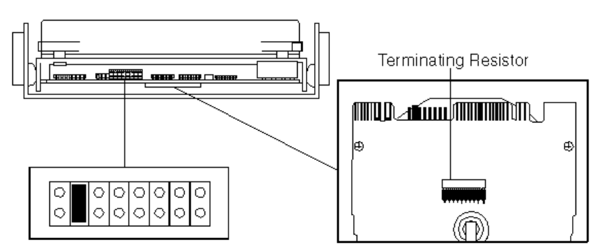
HP D1296A/D1297A 20/40 MB ST-225/ST-251 HARD DISK DRIVES
D1296A/D1297A Default Jumper Settings
If the hard disk drive is the second drive from the end of the cable, remove the terminating
resistor from the drive. (Remove the disk mounting tray to gain access to the terminating
resistor.)
Initializing ST-225/ST-251 Drives
Use the Setup program (versions B and C) to initialize the drives after replacement:
• Type
drive:\path\
SETUP /X [ENTER] to view the drive Defects List.
• Run option 4 of the Setup program to initialize the drive.
If additional defects are found during initialization, type
drive:\path\
SETUP /D [ENTER]
to enter a new Defects List manually.
HP D1445A/D1446A 108/152 MB ESDI HARD DISK DRIVES
The HP D1445A and D1446A ESDI drives have no user accessible switches or jumpers.
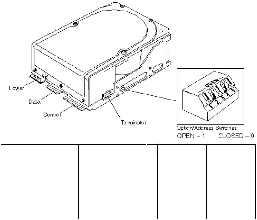
HP D1660A/61A (330/670 MB), HP D1674A/75A/76A (103/155/310 MB) ESDI
HARD DISK DRIVES
D1660A/61A and D1674A/75A/76A ESDI Drive Switch Bank
1234
5
ESDI Address
The default is 0
0 = Spin-up on power-on
enabled
1 = Spin-up on command
The default is 1
0 = Aggressive seeks
option disabled
1 = Aggressive Seeks
Option enabled
0
0
0
0
1
1
1
1
0
0
1
1
0
0
1
1
0
1
0
1
0
1
0
1
Illegal
2 (default)

HP IDE HARD DISK DRIVES
This section describes the following IDE hard disk drives:
Part Number Description Page
D2328-6000x 40 MB IDE hard disk drive 5-24
D2387-60101 210 MB Fast IDE hard disk drive 5-28
D2390A 270 MB IDE hard disk drive 5-27
D2391A 540 MB IDE hard disk drive 5-27
D2392-6xxxx 420 MB IDE hard disk drive 5-29
D2393-6xxxx 840 MB IDE hard disk drive 5-29
D2394-6xxxx 360 MB IDE hard disk drive 5-32
D2395-6xxxx 540 MB IDE hard disk drive 5-32
D2396-6xxxx 720 MB IDE hard disk drive 5-32
D2890-60101 340 MB Fast IDE hard disk drive 5-28
D2891A/B 540 MB IDE hard disk drive 5-27
D2894A/B 270 MB IDE hard disk drive 5-27
D2906-6xxxx 420 MB IDE hard disk drive 5-28
D2916-6xxxx 420 MB IDE hard disk drive 5-34
D2927-6xxxx 1.6 GB IDE hard disk drive 5-29
D2928-6xxxx 2 GB IDE hard disk drive 5-35
D2939-6xxxx 630 MB IDE hard disk drive 5-28
D3032-6xxxx 106 MB IDE hard disk drive 5-24
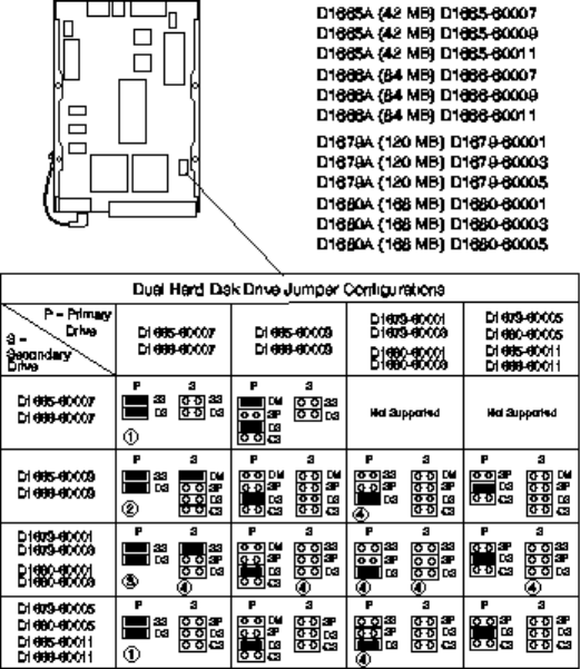
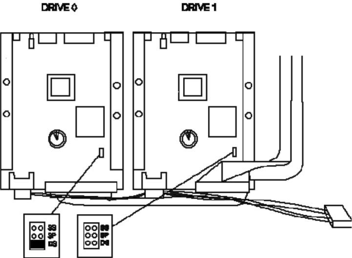
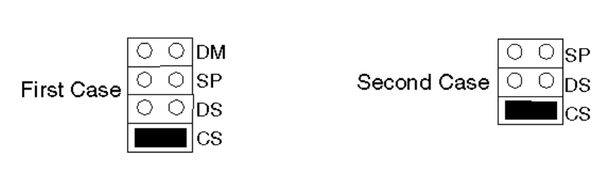
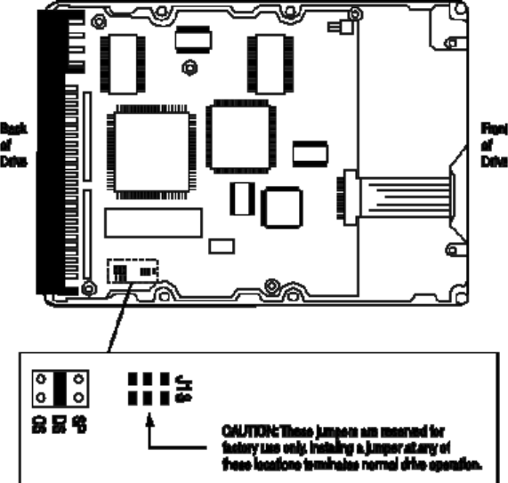
HP D1665A/D1666A (42/84 MB) AND
HP D1679A/D1680A (120/168 MB)
If only one hard disk drive is used, set the “DS” jumper only.
42/84/120/168 MB IDE Drive Default Jumpers
1 Remove jumper from secondary drive and place on SS pins of primary drive
2 Use extra jumper provided on D1665-60009 and D1666-60009 drives
3 Use extra jumper on primary drive provided on D1679A or D1680A
4 “SS” jumper may be labeled “TM”
HP D1688A DUAL 168 MB IDE HARD DISK DRIVE
HP D1688A Drive Default Jumper Settings
The D1688A is a dual 168 MB (D1680A) disk drive.
For more information on the jumper settings, refer to the section “HP D1665A/D1666A,
D1679A/D1680A 42/84, 120/168 MB IDE Hard Disk Drives”.
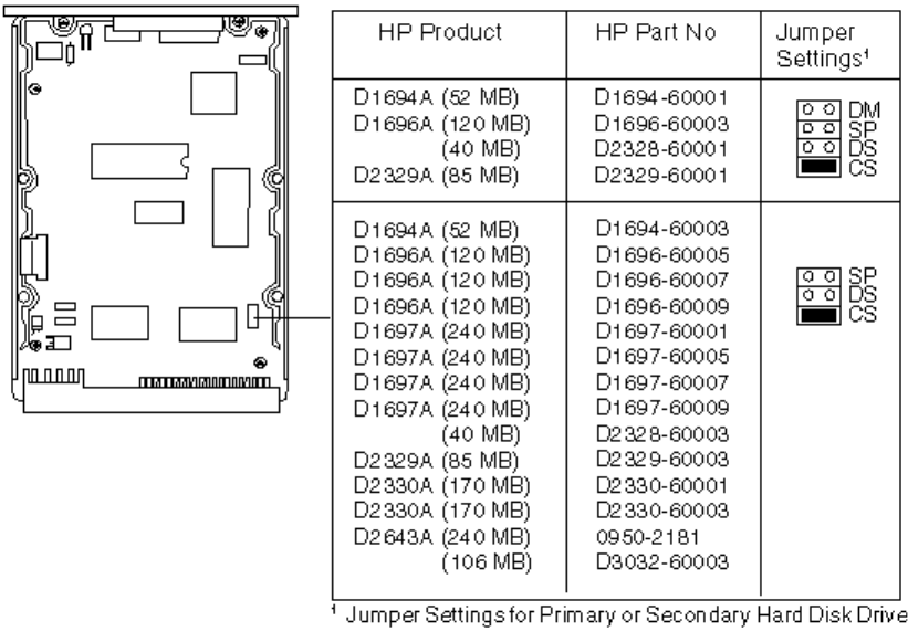
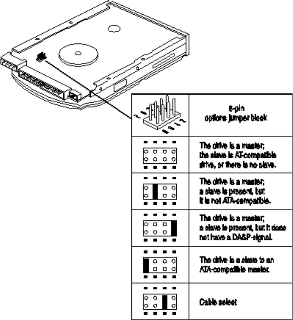
HP D1694A/96A/97A OR D2643A (52/120/240 MB),
HP D2329A/30A (85/170 MB),
HP D2328-60001/3 (40 MB), AND
HP D3032-60003 (106 MB) IDE HARD DISK DRIVES
Whether one or two disks drives, and HP supplied cables are used, the “CS” jumper must
always be set. See the Vectra part list in the
Vectra PC Service Handbook
.
52/120/240 and 40/85//106/170 MB IDE Drive Default Jumpers
• The D2328-60001/3 (40 MB) hard disks do not have HP product numbers. They are
supported under D1694A.
• The D3032-60003 (106 MB) hard disk does not have an HP product number. It is
supported under D1696A.
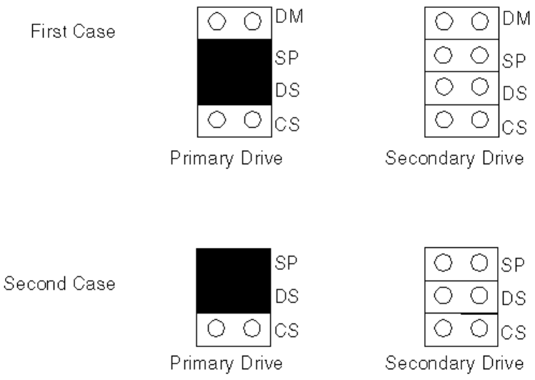
Configuring Without Cable Select
Some D1665A, D1694A, and D1666A hard disk drives may not support the cable select
feature. If a D2884A is installed with one of these drives it may be necessary to disable cable
select.
To disable cable select on a D1665A, D1694A, or D1666A, remove the cable select jumper
(marked CS) and configure the drive as the primary or secondary drive.
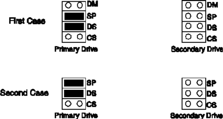
Disabling Cable Select on D1665A, D1694A, and D1666A
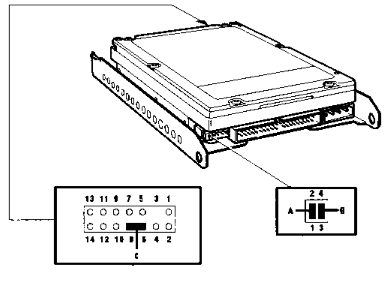
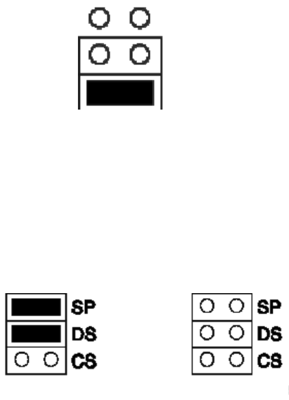
HP D2884A 450 MB IDE HARD DISK DRIVE
The HP D2884 is preconfigured to use a cable select feature, which determines which drive is
the primary or secondary drive.
To disable cable select on the D2884A hard disk drive:
1 Remove the cable select jumper (marked C in the diagram below) from the HP D2884A.
2 Configure the HP D2884A as the primary or secondary drive. Remove jumper A to identify
the drive as the primary or remove jumper B to identify the drive as the secondary.
Location of configuration jumpers on the D2884A
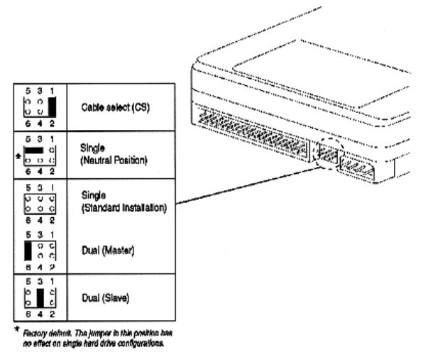
HP D2330B (170 MB), HP D2387A (210 MB),
HP D2890A (340 MB), HP D2891A/B (540 MB) AND
HP D2894A/B (270 MB) IDE HARD DISK DRIVES
For D2387-60101 and D2890-60101, refer to the next page.
Factory Standard Setting for Cable Select Jumper
Cable Select on D2330B, D2387A, D2894A/B, D2890A, and D2891A/B
The HP D2330B, D2387A, D2890A, D2891A/B, and D2894A/B drives are preconfigured to use
the cable select feature, which determines which drive is the primary or secondary drive. There
is one jumper on the drive but this must left in its current position.
Disabling Cable Select
If the cable used does not support cable select, it will be necessary to disable the cable select
feature.
To disable cable select on a D2330B, D2387A, D2894A/B, D2890A, or D2891A/B, remove the
cable select jumper (marked CS) and configure the drive as the primary or secondary drive.
Disabling Cable Select on D2330B, D2387A, D2894A/B, D2890A, and D2891A/B
HP 106 MB FAST IDE D3032-60031
HP 210 MB FAST IDE D2387-60101
HP 340 MB FAST IDE D2890-60101
HP 420 MB FAST IDE D2906-60XXX
HP 270/540 MB FAST IDE D2390/1-60001
HP 630 MB FAST IDE D2939-6XXXX
For D2387A and D2890A, refer to the previous page.
Whether or not two drives, or HP supplied cables, are used, the cable select jumper should
always be set.
HP D2392-6XXXX 420 MB ENHANCED IDE
HP D2393-6XXXX 840 MB ENHANCED IDE
HP D2927-6XXXX 1.6 GB IDE HARD DISK DRIVES
Whether or not two drives, or HP supplied cables, are used, the cable select jumper, (position
3 - 4) should always be set.
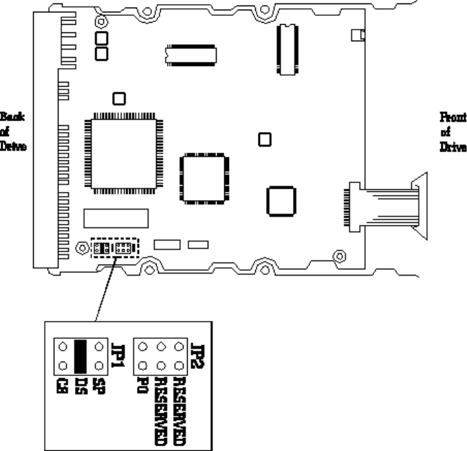
HP D2388A 270 MB IDE HARD DISK DRIVE
HP D2389A 540 MB IDE HARD DISK DRIVE
Whether or not two drives, or HP supplied cables, are used, the cable select (CS) jumper
should always be set.
The configuration of the three jumpers controls the drive’s mode of operation:
•CS - Cable Select
•DS - Drive Select
•SP - Slave Present.

CS* DS* SP* Description
0 0 0 Slave Drive
Compatible with drives using the PDIAG- line to handle Master/Slave
communications.
0 0 1 Slave Drive
The PDIAG- and DASP- lines are not driven.
0** 1** 0** Master Drive
Uses DASP- to check for the presence of a Slave.
0 1 1 Master Drive
Uses the SP jumper to determine whether a Slave is present, without
checking PDIAG- or DASP-.
1 0 X Slave or Master Drive, depending on the state of the Cable Select signal
(pin 28) at the IDE-bus interface connector.
If the signal state is set to 0 (grounded), then the drive is configured as if
DS
*In the table above, 0 indicates that the jumper is removed, 1 indicates that the jumper is installed,
and X indicates that the jumper setting does not matter.
**This is the factory default setting
The CS and DS jumpers should never be installed at the same time.
HP D2394-6XXXX 360 MB IDE HARD DISK DRIVE
HP D2395-6XXXX 540 MB IDE HARD DISK DRIVE
HP D2396-6XXXX 720 MB IDE HARD DISK DRIVE
Whether or not two drives are used, or HP supplied cables, the cable select (CS) jumper
should always be set. For further information refer to the parts list in the
Vectra PC Service
Handbook
.
The configuration of the following four jumpers controls the drives mode of operation:
• CS - Cable Select
• DS - Drive Select
• SP - Slave Present
• PO - Product Option.

CS DS SP Description
0 0 0 Slave Drive. Compatible with drives using the PDIAG- line to handle
Master/Slave communications.
0 1 0 Master Drive (or Single Drive). Uses DASP- to determine whether a
Slave is present. (Factory default settings.)
0 1 1 Master Drive (in PDIAG- mode). Uses the SP jumper to determine
whether a Slave is present, without checking DASP_.
1 0 X Master or Slave Drive, depending on the state of the Quantum Cable
Select signal (pin 28) at the AT-bus connector.
If the Cable Select signal is set to 0 (grounded), then the drive is
configured as if DS were 1, as described earlier. If the Cable Select
signal is set to 1 (high), then the drive is configured as if DS were 0,
as described earlier.
In the above table 0 indicates that the jumper is removed and
1 indicates that the jumper is installed.
The CS and DS jumpers should not be installed at the same time.
HP D2916-6XXXX 420 MB IDE HARD DISK DRIVE
HP D2918A 540 MB IDE HARD DISK DRIVE
HP D2929A 630 MB IDE HARD DISK DRIVE
HP D2919A 1 GB IDE HARD DISK DRIVE
HP D2930A 1.2 GB IDE HARD DISK DRIVE
HP D2925A 840 MB IDE HARD DISK DRIVE
Factory Standard Setting for Cable Select Jumper
SP
DS
CS
Cable Select
These drives are preconfigured to use the cable select feature, which determines which drive is
the master (primary) or slave (secondary) drive. There is one jumper on the drive but this must
left in its current position.
Disabling Cable Select
If the cable used does not support cable select, disable the cable select feature. To do this,
remove the cable select jumper (marked CS) and configure the drive as the master or slave
drive.
Master Drive Slave Drive
Disabling Cable Select
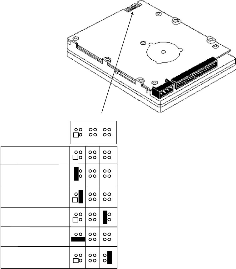
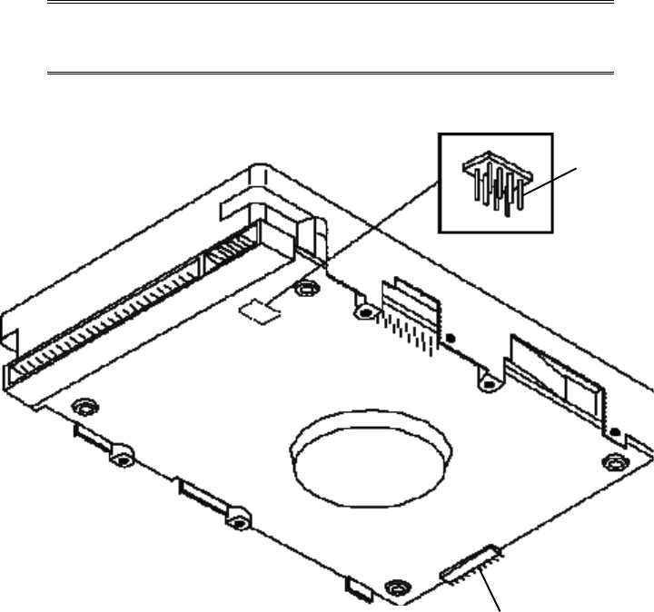
HP D2928-6XXXX 2 GB IDE HARD DISK DRIVE
Use pins 11 and 12 to connect the remote drive activity light to this drive.
One drive only
Drive is slave
Drive is master;
slave is present
Cable Select (default)
Spares
Drive activity light connector
pin 11 (-), pin 12 (+)
2 4 6 8 10 12
1 3 5 7 9 11
HP SCSI MASS STORAGE DRIVES
This section describes the following SCSI hard disk drives:
Part Number
Description Page
440 MB SCSI hard disk drive 5-37
670 MB SCSI hard disk drive 5-39
1 GB SCSI hard disk drive 5-39
430 MB SCSI hard disk drive 5-41
430 MB SCSI hard disk drive 5-41
535 MB Fast SCSI-2 hard disk drive 5-43
D2076A/B
1053 MB Fast SCSI-2 hard disk drive 5-43
270 MB SCSI-2 hard disk drive 5-45
540 MB SCSI-2 hard disk drive 5-45
D2398-6xxxx
540 MB SCSI-2 hard disk drive 5-46
1 GB SCSI hard disk drive 5-42
1 GB SCSI hard disk drive 5-42
D2904-6xxxx
1 GB SCSI-2 hard disk drive 5-47
1 GB SCSI-2 hard disk drive 5-49
2 GB SCSI-2 hard disk drive 5-51
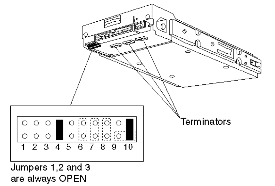
HP D1685A 440 MB SCSI HARD DISK DRIVE
D1685A SCSI Drive Option Jumpers
The Default SCSI address is 0.
If this is the only SCSI disk drive (and there are no external SCSI devices attached), it should
be set to SCSI address 0 and terminated.
If it is the second SCSI disk drive, it should be set to SCSI address 1 and not terminated.
D1685A Jumpers
0 signifies a NO jumper (open circuit)
1 signifies a CLOSED jumper
Option Jumpers 1 to 3
1 2 3 Not used, always 0
Option Jumpers 4 to 8
4 5 6 7 8 SCSI
Address
The default is 1
0 = Parity
checking disabled
1 = Parity
checking enabled
The default is 0
0 = Spin-up at
power-on enabled
1 = Spin-up on
command
0 0 0 0 (default)
001 1
010 2
011 3
100 4
101 5
110 6
111 7
Option Jumpers 9 and 10
9 10 Function
1 0 Terminator power supplied from drive power cable
01
Terminator power supplied to SCSI bus - default
Both shorted together Terminator power supplied from SCSI bus
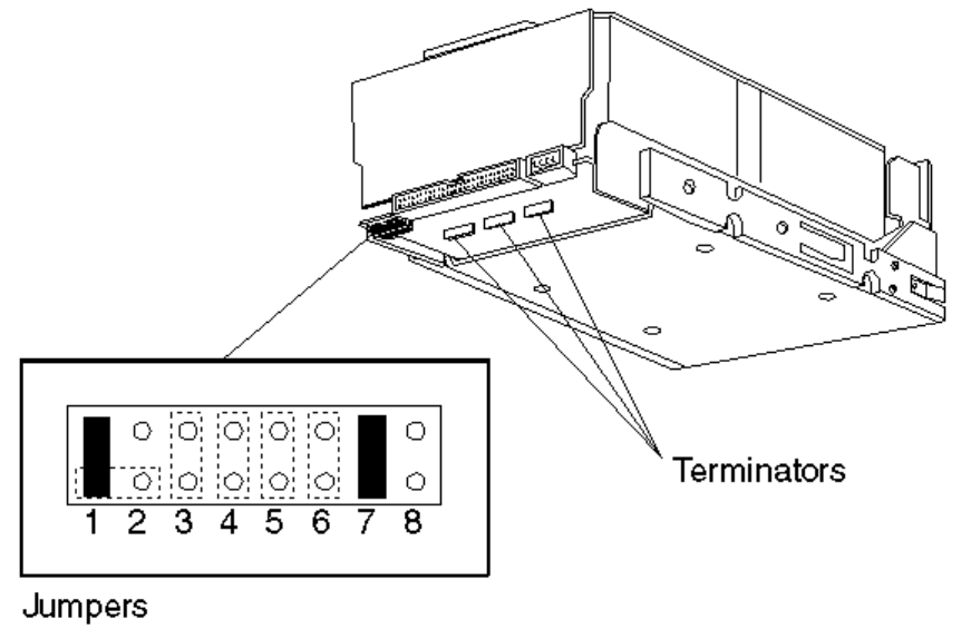
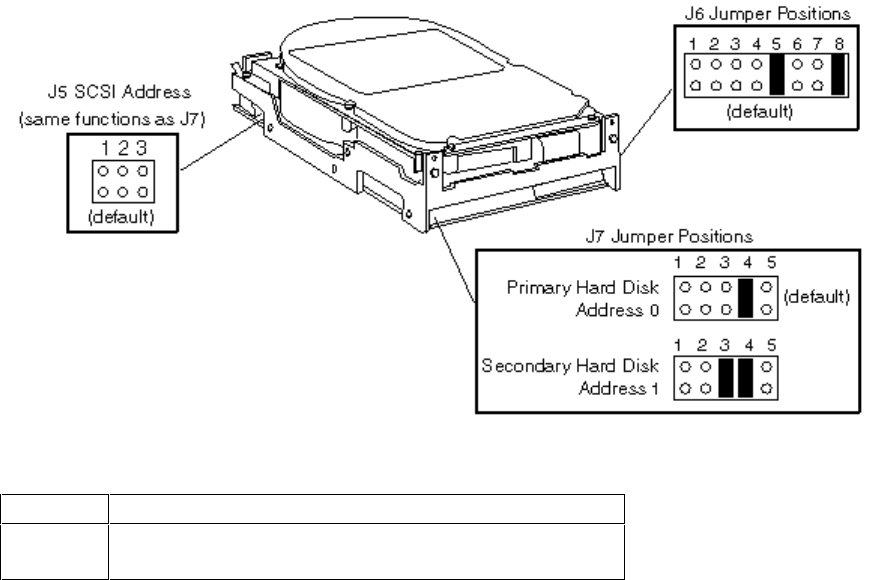
HP D1686A/D1687A 670/1000 MB
SCSI HARD DISK DRIVES
D1686A/7A SCSI Drive Option Jumpers
The Default SCSI address is 0. If this is the only SCSI disk drive, and no external SCSI devices
are attached, it should be set to SCSI address 0, and terminated. If it is the second SCSI disk
drive, it should be set to SCSI address 1, and not terminated.
D1686A/87A Jumpers
0 signifies a NO jumper (open circuit)
1 signifies a CLOSED jumper
Option Jumpers 1 and 2
1 2 Function
1 0 Terminator power supplied from drive power cable -
default
Both shorted together Terminator power supplied from SCSI bus
Option Jumpers 3 to 8
SCSI
Address 345 6 7 8
0 (default) 000Default 0
0 = Spin- up
at power-on
enabled
1 = Spin- up
on command
Default 1
0 = Parity
checking
disabled
1 = Parity
checking
enabled
Always 0
1001
2010
3011
4100
5101
6110
7111
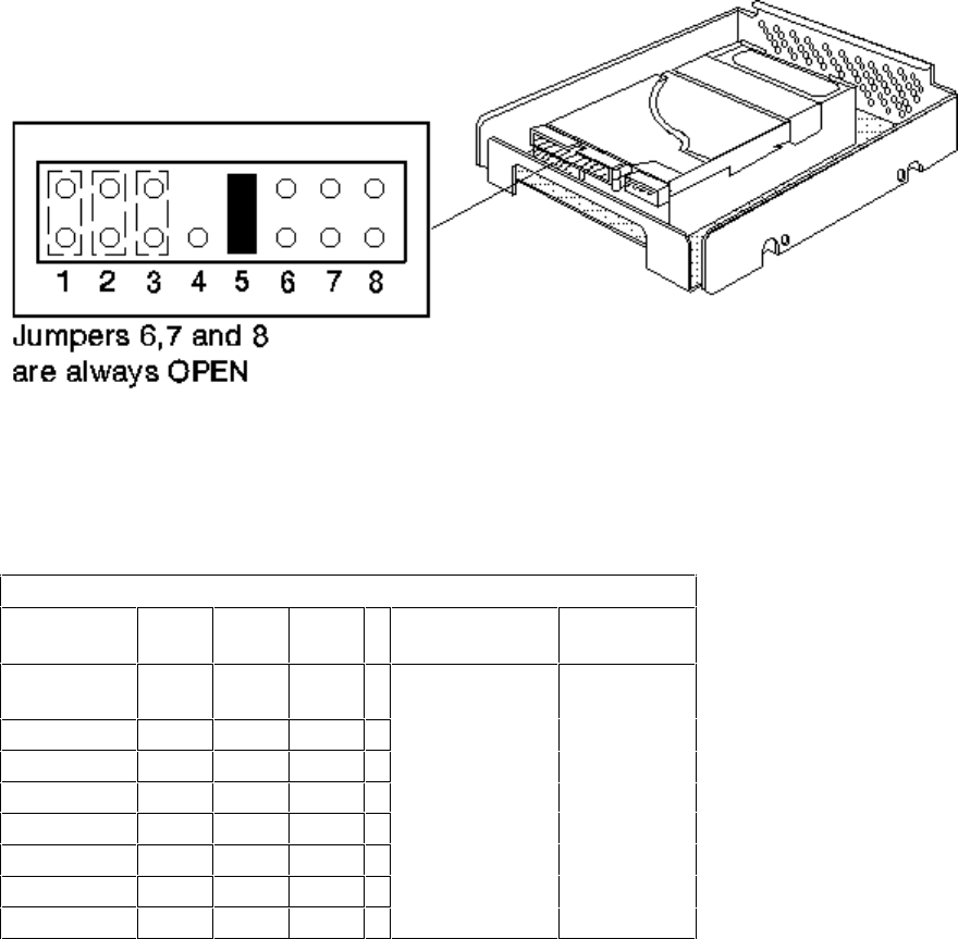
HP D1699A/D2644A 430 MB SCSI HARD DISK DRIVE
D1699A/D2644A Jumper J6 Default Settings
Jumper Description
5 Enable parity checking
8 Terminator power source is the drive
HP D2645A/D2653A 1000 MB SCSI HARD DISK DRIVE
D2645A/D2653A SCSI Drive Option Jumpers
D2645A/D2653A Jumpers
0 signifies a NO jumper (open circuit)
1 signifies a CLOSED jumper
Option Jumpers 1 to 5
SCSI
Address 123 4 5
0 (default) 0 0 0 Not used Must be 1
(default)
1001
2010
3011
4100
5101
6110
7111
The D2645A is the same as the D2653A, but with additional rails for external storage solution.
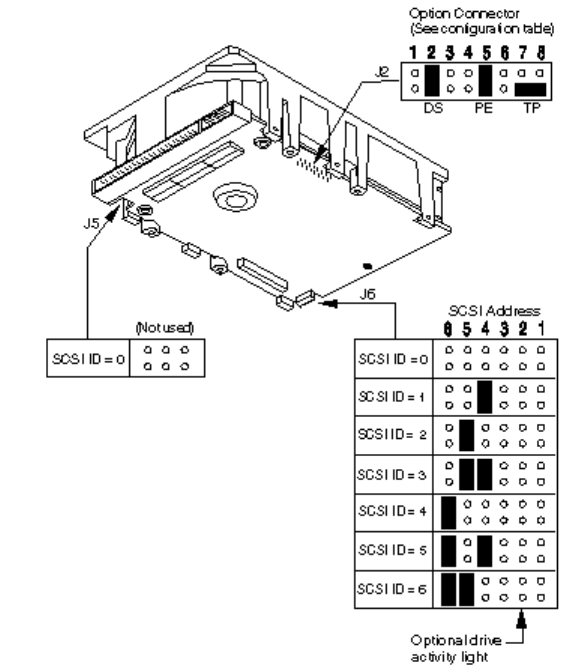
HP D2075A/D2076A/B 535/1035 MB SCSI-2
HARD DISK DRIVES
The Default SCSI address is 0.

J2-Option connector configuration
Name Pins Description
Reserved 1 This pinset is not used and must remain open.
Delay Spinup (DS) 2 Open - The drive spins up at power on if there is no jumper
on pinset 3.
Closed - The drive waits a number of seconds before it
spins up (8 x SCSI-ID seconds) to reduce the current
demand spinning up several drives simultaneously.
Motor Start 3Open - The drive checks pinset 2 to determine if it
should spin up immediately or delay the spin up.
Closed - The drive waits for a Unit Start command from the
host before starting the drive motor.
Write Protect 4Open - Write protect mode is disabled. The drive
should be left in this mode.
Closed - Write protect mode is enabled. Data cannot be
written to the drive.
Parity (PE) 5Open - Parity checking disabled.
Closed - Parity checking enabled.
Reserved 6 This pinset is not used and must remain open.
Terminator Power
(TP) 7, 8 Note: Terminators are NOT installed on these drives. These
drives have been designed for use on a SCSI cable with a
built-in terminator. If the SCSI cable used does not have a
terminator, the SCSI device closest to the free end of the
cable MUST be terminated.
Jumpers at these positions determine the terminator power
source. If a jumper is installed on pinset 7, the drive supplies
power to the SCSI bus pin 26. If a jumper is installed on
pinset 8, the drive only supplies power to its own terminators.
A jumper installed horizontally on the lower pins of
pinsets 7 and 8 (default), allows the drive to take power
from the SCSI bus pin 26.
HP D2385-60001 270 MB SCSI-2
HP D2386A 540 MB SCSI-2
HARD DISK DRIVES
SCSI ID 0 1 2
4
Jumper Setting
The Default SCSI address is 0.
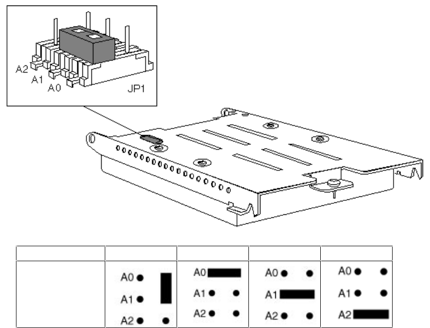
HP D2398-6XXXX 540 SCSI-2 MB HARD DISK DRIVE
Jumper Settings SCSI ID
A2 A1 A0
OFF OFF OFF 0 (Default)
OFF OFF ON 1
OFF ON OFF 2
OFF ON ON 3
ON OFF OFF 4
ON OFF ON 5
ON ON OFF 6
ON ON ON 7
“ON” indicates that a jumper is installed and “OFF” that no jumper is installed.
If J5 is being used for the SCSI ID, do not install a jumper on A2, A1 or A0, as they are
available at more than one location.
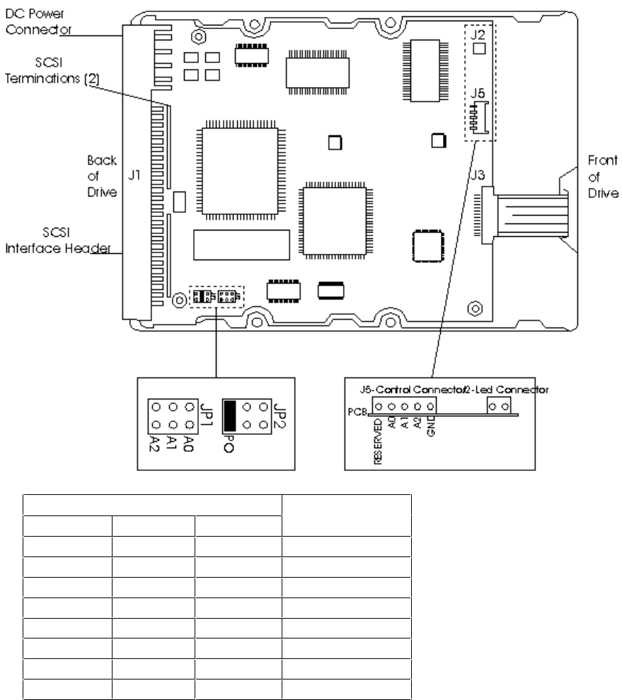
HP D2904-6XXXX 1GB SCSI-2 HARD DISK DRIVE
Either J5 or J6 may be used to select the Drive ID, but not both at the same time. The default
ID is 0.
If you use J6, do not set a jumper between pins 3 - 4.

J2 Jumper
Installation Jumper Function Description
TE Applies only to “N” models.
On The On-board , non-removable terminator circuits are enabled with the
jumper installed. (Connected to the I/O lines.) The default is the jumper is
installed.
Off The terminator circuits are not connected to I/O lines.
DS ME
Off Off Spindle starts immediately after power up. Default setting.
Off On Drive spindle does not start until Start Unit command is received from host.
On Off Spindle Startup is delayed by SCSI Id times 12 seconds after power is
applied, that is, drive 0 spindle starts immediately DC power is connected
and drive 1 starts after a 12 second delay, drive 2 starts after a 24 second
delay and so on.
On On Drive spindle starts when Start Unit command is received from host. Delayed
start feature is overridden and does not apply when ME jumper is installed.
WP
On Entire drive is write protected.
Off Drive is not write protected. Default is no WP jumper installed.
PE
On Parity checking and parity error reporting by the drive is enabled. Default is
PE jumper installed.
Off Drive does not report result of parity checking to host.
SS
Off Reserved jumper position. Default is no jumper installed.
TP TP Not used on “NC” models.
Off Off No terminator power is connected to drive terminators or SCSI bus I/O pin
26.
On Off Drive supplies its own terminator power only. Jumper on this position is
factory default.
Off On Drive supplies power to I/O pin 26 of SCSI bus, none to terminators. When
drives have differential I/O circuits, a jumper on the right TP position may be
needed to power external terminators. (Refer to system documentation.) The
“ND” drive has differential I/O circuits which have no terminator circuits on
the drive. The model “NC” has no provision for terminators on the drive or for
terminator power on the 80 pin I/O connector.
On On Drive supplies terminator power to itself (internal connection) and to I/O pin
26 of the SCSI bus. This is a legal jumper setting.
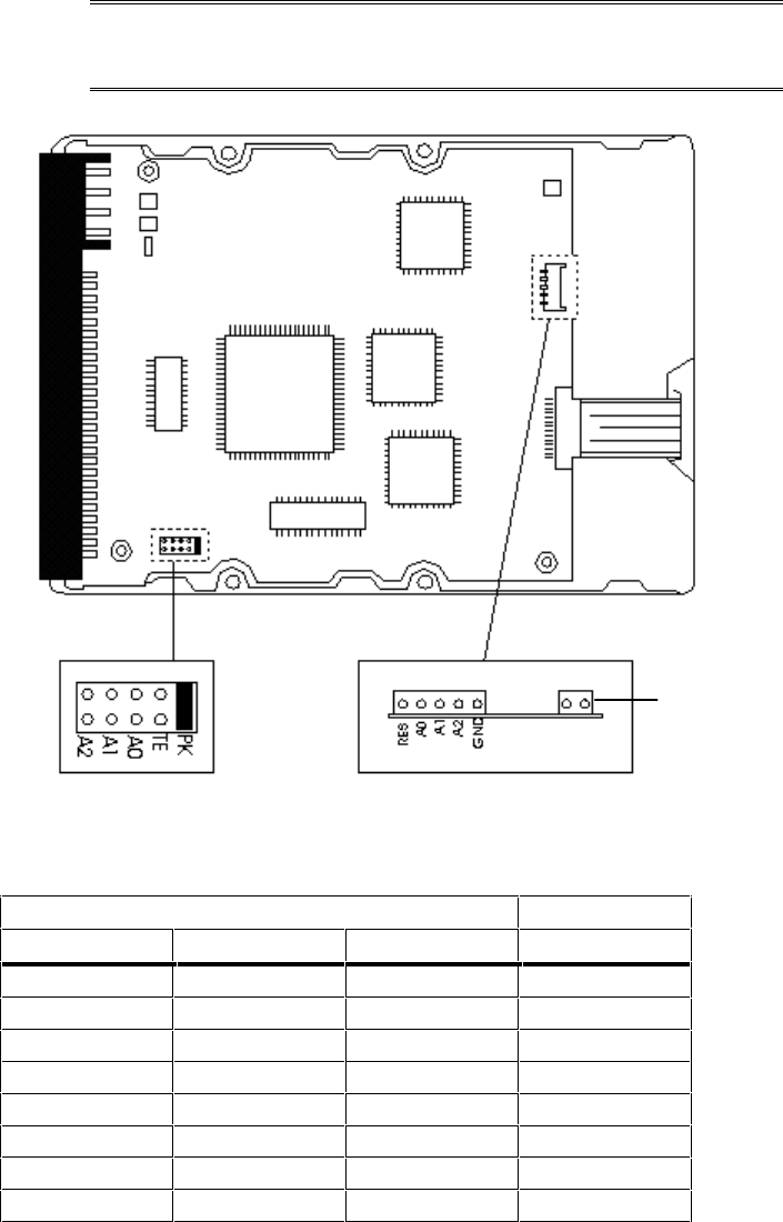
HP D2920A 1 GB FAST SCSI-2 HARD DISK DRIVE
NOTE: This drive requires a SCSI cable active termination
(P/N 0960-0888), provided with HP Vectra XU 5/xx
and XU 6/xxx series.
J2
Light Connector
J5
Optional Jumpers
(Not supported)
J1
SCSI ID Set
J1* SCSI ID
A2 A1 A0
OFF OFF OFF 0**
OFF OFF ON 1
OFF ON OFF 2
OFF ON ON 3
ON OFF OFF 4
ON OFF ON 5
ON ON OFF 6
ON ON ON 7***
*ON =Jumper Installed: OFF = Jumper not Installed
**ID Default Setting
***Reserved for SCSI Controller. Do not use.

If your PC has a terminated cable connected to an integrated SCSI interface, disable the
termination option (TE) on J1.
Jumper Settings
Jumper
Locations ON* OFF
J1 Option Jumpers
Termination
Enable (TE) This function enables termination. Disabled by default.
(No jumper)
Jumper Parking
Position (PK) A spare jumper is stored here by default.
SCSI
IDs(A2,A1,A0) Use to set SCSI ID.Refer to table on
previous page.
J2 Option Connectors
Light Connector Drive activity light connected. Not connected.
J3 Control Connectors (Feature not
supported)
Reserved (RES) This pin is reserved and should not be
used. (No jumper installed)
A2, A1, A0 Do not use. (No jumper installed)
GND Do not use.
*ON =Jumper Installed: OFF = Jumper not Installed
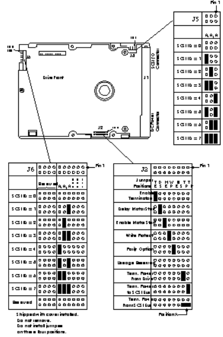
HP D2926A 2 GB FAST SCSI-2 HARD DISK DRIVE
NOTE: This drive requires a SCSI cable active termination
(P/N 0960-0888), provided with the HP Vectra XU
5/xx and XU 6/xxx series.
J1 Termination Setting
Back of Drive
Pin 1
J2 Option Settings
Front of
Drive
J4 SCSI ID/Option Settings
SCSI ID - 0
SCSI ID - 1
SCSI ID - 2
SCSI ID - 3
SCSI ID - 4
SCSI ID - 5
SCSI ID - 6
SCSI ID - 7
Reserved for
SCSI Controller
Default SCSI ID
(No Jumper Installed)
J4
Pins 7-12 control
the SCSI ID
Term. Power from Drive
Term. Power to SCSI Bus
Term. Power from SCSI Bus
Term. Power to SCSI
Bus & Drive
Enable the SCSI Terminator
J1 Pin 1
Pin 2
When the Enable
SCSI Terminator
jumper is set, you
must also install the
necessary jumper(s) to
select the terminator
power source.
Reserved
Disable Parity
Write Protect
Enable Motor Start
Delay Motor Start
J2 Pin 2
Pin 1
Reserved
Light Connector
Spindle Sync
Cable Connector
Front View of J4
J4
Pins 1 - 6
Pin 2
Pin 1

Jumper Settings*
JP1 Termination Configuration
Terminate Power from Drive Drive provides terminated power for optional internal
termination.
Terminate Power to SCSI Bus Drive supplies power to SCSI Bus. This is the default setting.
Terminate Power from SCSI Bus Drive accepts terminated power from SCSI Bus.
Terminate Power to SCSI Bus
and Drive Drive provides power to its own terminators and SCSI Bus.
Enable SCSI Terminator This pin-set enables internal SCSI termination.
JP2 Drive Configuration
Reserved Pins 1 - 2 & 14 - 20 are not used. (No jumpers)
Disable Parity Disables parity checking. The default setting is for this to be
enabled. (No jumper)
Write Protect Enables Write-protect mode. In this mode data cannot be
written to the drive. In most circumstances, this function
should remain disabled. (No jumper)
Enable Motor Start Controls immediate/delayed spin-up. The default setting is
for this to be disabled. (No jumper)
Delay Motor Start Controls immediate/delayed spin-up at power-on. The default
setting is for this to be disabled. (No jumper)
JP3 SCSI ID Set/Option Connectors
Reserved Pins 1 - 2 and 14 - 20 are not used. (No jumpers)
Light Connector Drive activity light connector. (No jumper)
Spindle Sync Cable Connector Optional Spindle Sync can be connected. (No jumper)
*The functions given in this table become active when jumpers are installed. Default settings are
indicated.

REPLACEMENT PART NUMBERS FOR MASS STORAGE DEVICES
Flexible Disk Drives
Product # Flexible Disk Drive Repl. P/N
Exch. P/N
-
-
-
(grey)
-
-
D2881B* Flexible Disk Drive 1.2 MB 51/4 in D2881-63101
(grey)
*Only used in Medium-Profile Vectra Box
CD-ROM Drives
Product # Disk Drive Repl. P/N
Exch. P/N
-
-
-
-
-
-
*Requires cable 5182-1085. For further information refer to the
HP Vectra PC Service Handbook.
Hard Disk Drives
Product # Hard Disk Drive Repl. P/N
Exch. P/N
MFM (ST-506) Hard Disk Drives
EDSI Hard Disk Drives

Hard Disk Drives (Continued)
Product # Hard Disk Drive Repl. P/N Exch. P/N
IDE Hard Disk Drives
None* IDE 40 MB Hard Disk same as D1694A
None** IDE 106 MB Hard Disk same as D1696A
*The 40 MB Drives P/N D2328-60001/3 are supported under D1694A
**The 106 MB Drive P/N D3032-60003 is supported under D1696A
***The 106 MB Drive P/Ns D3032-60021/23/31 are supported under P/N D3032-63031
****Not sold as a stand-alone accessory, only bundled with HP Vectra PCs.

Hard Disk Drives (Continued)
Product # Hard Disk Drive Repl. P/N Exch. P/N
IDE Hard Disk Drives (Continued)
D2927-6xxxx Fast IDE 840 MB Hard Disk D2927-63001 D2927-69001
D2928-6xxxx Fast IDE 2 GB Hard Disk D2928-63001 D2928-69001
D2939-6xxxx Fast IDE 840 MB Hard Disk D2939-63001 D2939-69001
SCSI Hard Disk Drives
D2385-6xxxx Fast SCSI-2 270 MB Hard Disk D2385-63001 D2385-69001
*Terminators for D1685A, D1686A, and D1687A:P/N = 1810-1176
**Not sold as a stand-alone accessory, only bundled with HP Vectra PCs
***Same as D2653A, Cable P/N = D2635-60026, Tray P/N = D2635-60027

6 HP DATA COMMUNICATIONS AND LAN ADAPTER
BOARDS
This chapter provides general information about HP data communication and LAN adapter
boards.
Terminal Multiplexer (D2040A)
Interface Boards (HP 24540B/41B)
EtherTwist PC Link Adapter Board (
HP 27245A, HP 27247A
, HP 27247B)
ThinLAN PC Adapter Board (HP 27250A)
Ethernet 10 BaseT Board (5063-8790) and BNC Coax Adapter (D3979A)
10/100 VG Selectable PCI LAN Adapter (J2585A)
Token-Ring Adapter board (HP D2378A)
Modems (HP 24550A and HP 24551A)
Replacement parts list
The following HP Vectra PCs have an Ethernet interface integrated on their system boards with
a twisted pair connection (these interfaces can be configured using the PC’s Setup program).
An optional coaxial adapter accessory board is available to provide a coaxial connection
(D2746A).
386/33 NI (D27xxA)
486 NI (D27xxA)
486 MI
486XM
486XM2
XP
XM 5/xx Series 3
The following HP Vectra PC has an Ethernet interface integrated on the system board with both
twisted pair and coaxial connections.
XU
TERMINAL MULTIPLEXER (D2040A)
PRODUCT INFORMATION
The HP D2040A Terminal Multiplexer (or “Mux”) is an input/ output device subsystem that
consists of a Mux adapter board (installed in the PC) and a remote terminal concentrator unit.
Each user has direct access to the system for a specified amount of time, so that users can
share data or serial peripherals from a single PC.
Each Mux adapter board can support a maximum of four 8-channel terminal concentrator units
(supporting up to 32 terminals per mux).
CONFIGURATION
The following are required to install the HP D2040A Mux:
• SCO® UNIX 3.2 Basic Operating System and Link Kit
• One of the four “second connector” interrupts (IRQ 10, IRQ 11, IRQ 12, or IRQ 15) is
available for the Mux (or Muxes) to use to ensure that this interrupt line does not conflict with
other I/O hardware products
• I/O mapping requires 64 KB of system memory.
For more information on how to install and troubleshoot the Mux, refer to the
HP D2040A
Terminal Multiplexer Installation and User’s Manual
.
General steps for installing the HP D2040A Mux are:
1. Install the Santa Cruz Operation® (SCO) UNIX operating system.
2. Install the SCO Link Kit if it is not already installed.
3. Install any third-party I/O device drivers. (Some third-party drivers specify the order in
which they must be installed. In such cases, follow the installation instructions for the third-
party driver, as the Mux software can be installed at any time.)
4. If you plan to use VP/ix, install it before you install the Mux.
5. Use the general instructions in the manual supplied with your PC for installing accessory
boards.
6. Turn the computer off, unplug it, and remove its cover.
7. Set the Mux’s rotary switches as specified below or as described in the Mux manual.
8. Insert the Mux adapter board into the I/O slot.
9. Replace the computer’s cover.
10.On the back of the PC, connect the host cable(s) from the Mux to the terminal
concentrator(s).
11.Connect the terminal(s) to the terminal concentrator(s).

12.Plug in the computer and the terminal(s).
13.Bring the SCO UNIX operating system up in System Maintenance mode.
14.Use the SCO UNIX “custom” utility to install the D2040A device driver software.
15.Reboot and run the SCO UNIX operating system.
16.Use the SCO UNIX “sysadmsh” utility to configure users and terminals.
17.Enable TTYs for a login.
SWITCHES
Set the rotary switches so that there is no conflict with system memory, the BIOS, or other
devices in the system.
Switches
H L Memory Address Notes
D 0 D00000-D0FFFF Factory Setting
D X DX0000-DXFFFF Recommended with multiple host adapters
E X EX0000-EXFFFF Alternate high memory setting
0 A 0A0000-0AFFFF Try if > 10 MB of memory installed and Hercules, CGA,
or no video adapter installed
0 B 0B0000-0BFFFF Try if > 10 MB of memory installed and no video adapter
installed
0 C 0C0000-0CFFFF Try if > 10 MB of memory installed
0 D 0D0000-0DFFFF Try if > 10 MB of memory installed
0 E 0E0000-0EFFFF Try if > 10 MB of memory installed
I/O INTERRUPTS AND MEMORY MAPS
One of Interrupts 10, 11, 12 or 15 must be available for use with the board. The system
automatically selects the interrupt.
CONFIGURATION FILES
The configuration file is: !HWP1440.CNF
DRIVERS AND UTILITIES
Refer to the manual that came with the software or the
HP D2040A Terminal Multiplexer
Service Manual
for more information on integrating the board with the software.

INTERFACE BOARDS (HP 24540B AND HP 24541B)
Discontinued February 1995
PRODUCT INFORMATION
The HP 24540B and HP 24541B interface boards are “half-length” boards each equipped with
two data communications ports. The boards are used to increase the number of serial or
parallel devices that can be attached to the Vectra PC.
• The HP 24540B (serial/parallel board) has:
• one 9-pin, RS-232-C serial asynchronous port
• one 25-pin, 8-bit parallel port (Centronics-compatible).
• The HP 24541B (dual serial board) has:
• one 9-pin, RS-232-C serial asynchronous port
• one 25-pin, RS-232-C/HP 422 serial asynchronous port.
Specifications for Datacommunications Parameters
Parameter Specification
Baud Rate From 2 to 19200 baud
Parity Even, Odd, or None
Character Length 5, 6, 7, or 8 bits
Stop bits 1, 1.5, or 2 stop bits
Access to control
monitoring of the
RS-232 modem
control lines
• Data Terminal Ready
• Request to Send
• Clear to Send
• Data Set Ready
• Data Carrier Detect
• Ring Indicator
• Data Signal Rate Selector (25-pin of 24541B board only)
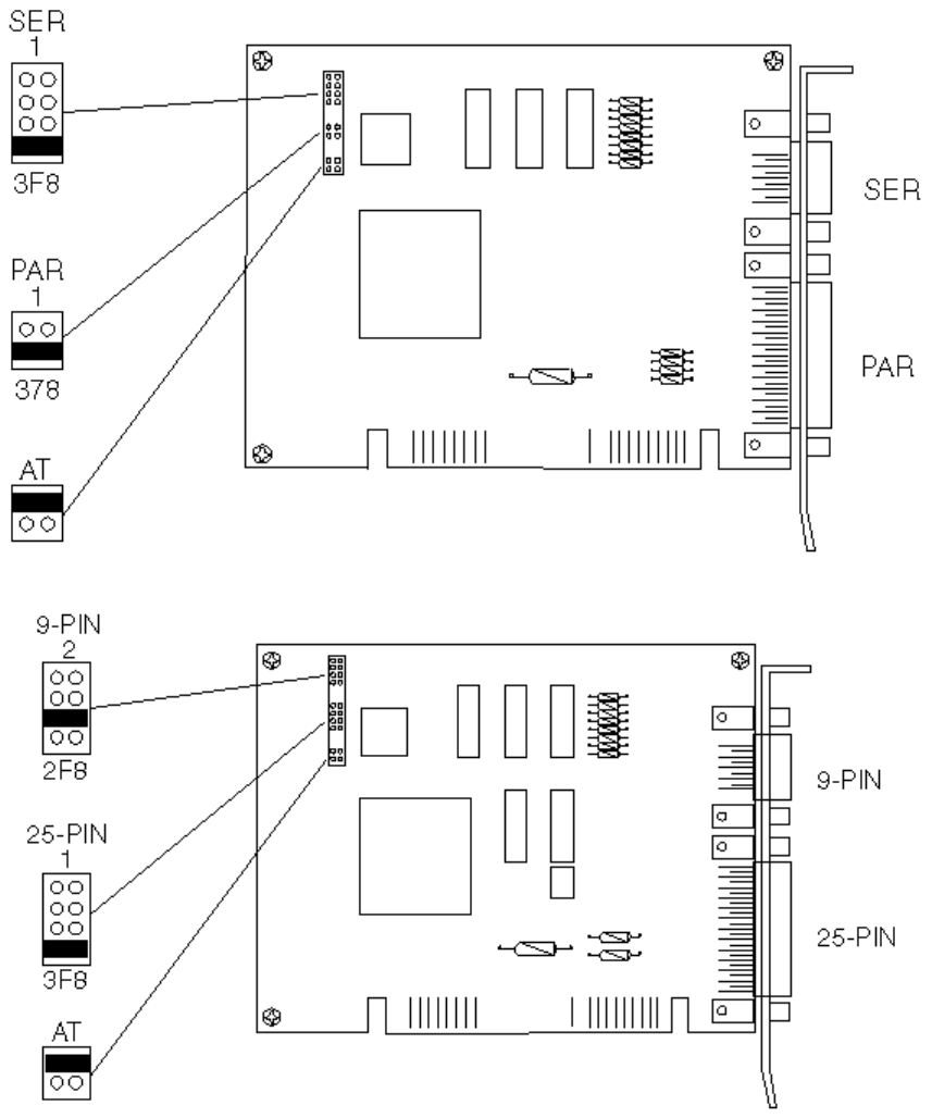
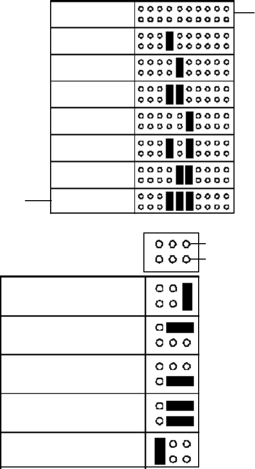
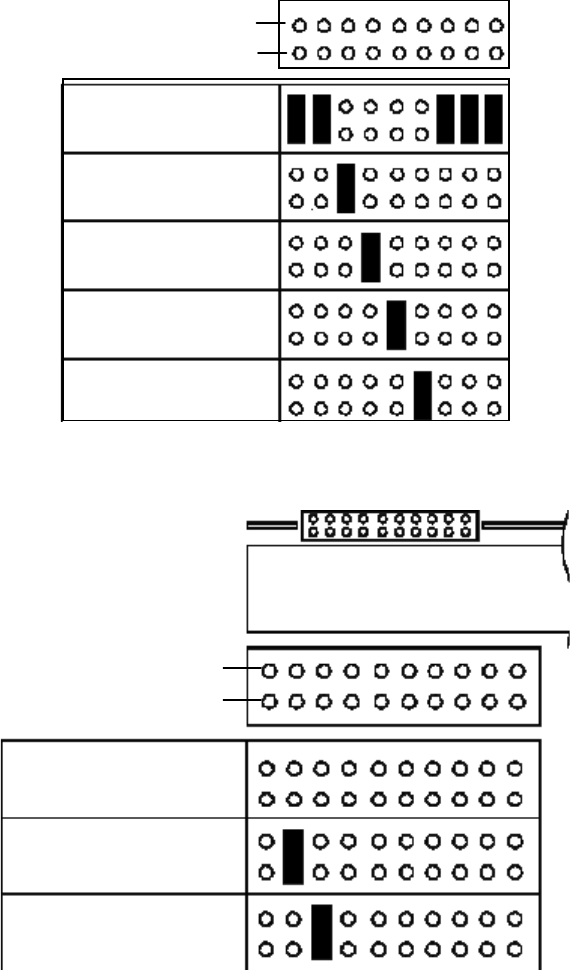
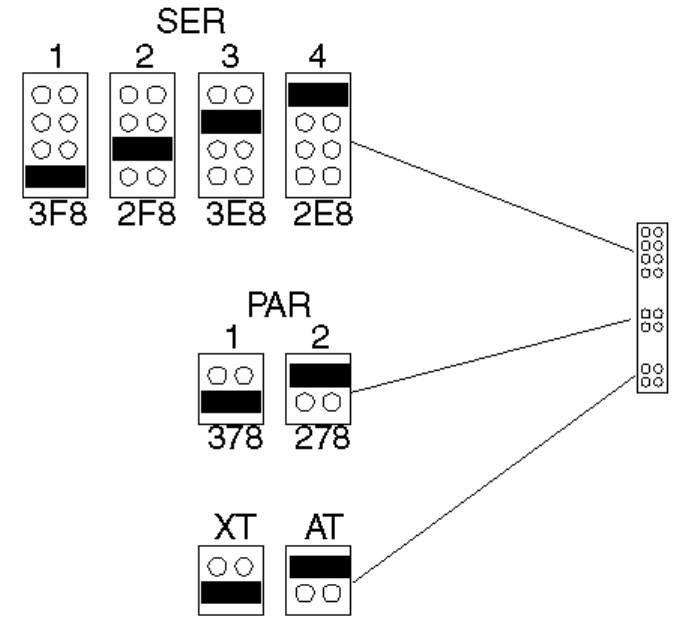
Jumpers on HP 24540B Serial Parallel Interface (Defaults)
Jumpers on HP 24541B Dual Serial Interface (Defaults)
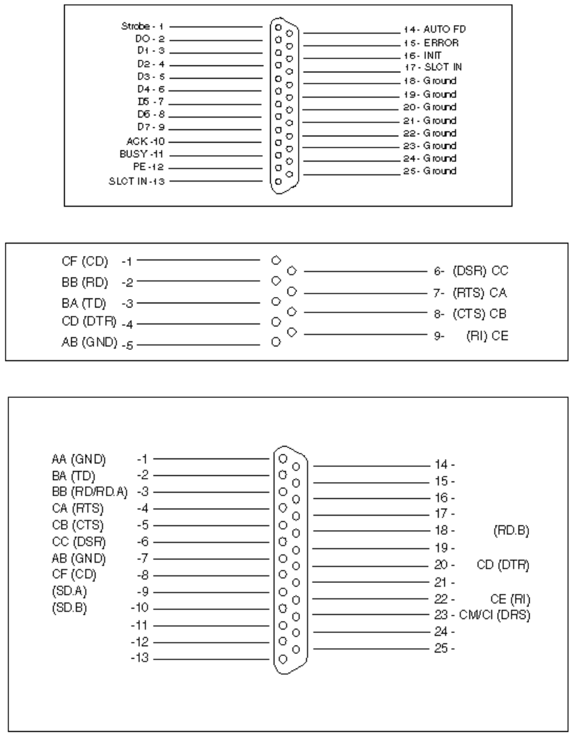
HP 24540B 25-pin Parallel Connector Pinouts
HP 24540B/1B 9-pin Serial Connector Pinouts
HP 24541B 25-pin Serial Connector Pinouts
CONFIGURATION
HP 24540B Jumpers
1. The 9-pin serial connector can be configured as either:
•Serial port 1 (COM1, default) using IRQ4 (3F8h)
•Serial port 2 (COM2) using IRQ3 (2F8h)
•Serial port 3 (COM3) using IRQ10 (3E8h)
•Serial port 4 (COM4) using IRQ11 (2E8h).
or disabled when no jumper is installed.
2. The 25-pin parallel connector can be configured as either:
•Parallel port 1 (LPT1, default) using IRQ7 (378h)
•Parallel port 2 (LPT2) using IRQ5 (278h)
or disabled when no jumper is installed.
3. The board can be configured to operate in either:
•An IBM AT-compatible computer, such as the Vectra (default)
•An IBM XT-compatible computer.
HP 24540B Jumpers
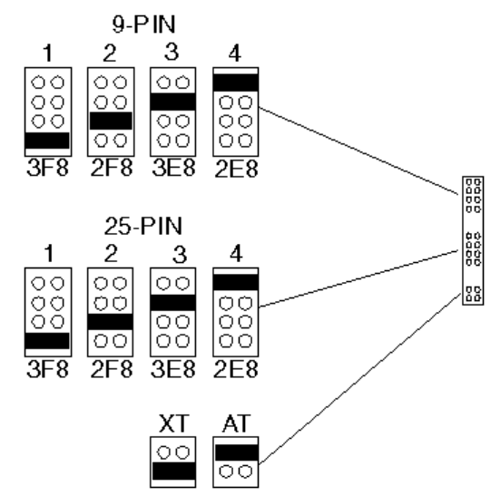
HP 24541B Jumpers
1. The 9-pin serial connector can be configured as either:
•Serial port 1 (COM1) using IRQ4 (3F8h)
•Serial port 2 (COM2, default) using IRQ3 (2F8h)
•Serial port 3 (COM3) using IRQ10 (3E8h)
•Serial port 4 (COM4) using IRQ11 (2E8h).
or disabled when no jumper is installed.
2. The 25-pin serial connector can be configured as either:
•Serial port 1 (COM1, default) using IRQ4 (3F8h)
•Serial port 2 (COM2) using IRQ3 (2F8h)
•Serial port 3 (COM3) using IRQ10 (3E8h)
•Serial port 4 (COM4) using IRQ11 (2E8h).
or disabled when no jumper is installed.
3. The board can be configured to operate in either:
•An IBM AT-compatible computer, such as the Vectra (default).
•An IBM XT-compatible computer.
HP 24541B Jumpers

I/O INTERRUPTS AND MEMORY MAPS
The boards can use the following I/O space and interrupts:
I/O Map
Setting I/O Address Used IRQ Used
COM1 3F8-3FF 4
COM2 2F8-2FF 3
COM3 3E8-3EF 10
COM4 2E8-2EF 11
LPT1 378-37F 7
LPT2 278-27F 5
CONFIGURATION FILES
The HP 24540B configuration file is: !HWP1C00.CNF The HP 24541B configuration file is:
!HWP1400.CNF
DRIVERS AND UTILITIES
communications ports. Refer to the MS-DOS manual.
TROUBLESHOOTING TIPS
•Check the board is correctly seated in the computer and correctly configured (no conflicts
with other boards).
•Test the datacomm ports using the diagnostic disk.
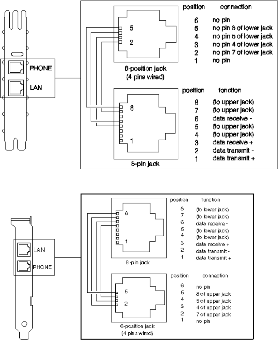
ETHERTWIST PC LINK ADAPTER BOARD (HP 27245A/7A/7B)
Product Information
The HP 27245A EtherTwist PC Link board is an 8-bit board that allows the Vectra PC to be
connected to a 10BASE-T network.
The HP 27247A and HP 27247B EtherTwist PC Link 16 boards are 16-bit boards that allow the
Vectra PC to be connected to a Type 10BASE-T network.
The three boards are equipped with:
•A LAN connector for a twisted-pair LAN cable.
•A telephone connector for a telephone system which has been integrated in the Type
10BASE-T network.
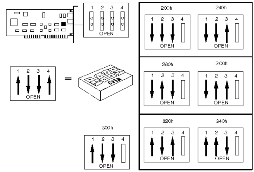
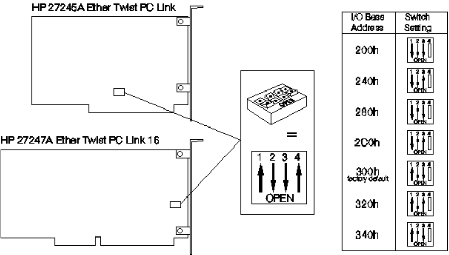
The HP 27245A board may have DIP switches or a rotary switch. The HP 27247A board has
DIP switches only.
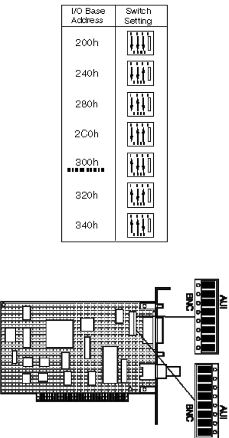
1. If the board has DIP switches (HP 27245A or HP 27247A) select:
•The I/O base address on switches 1, 2, and 3 (default: 300h).
•The link beat on switch 4 (default: ON).
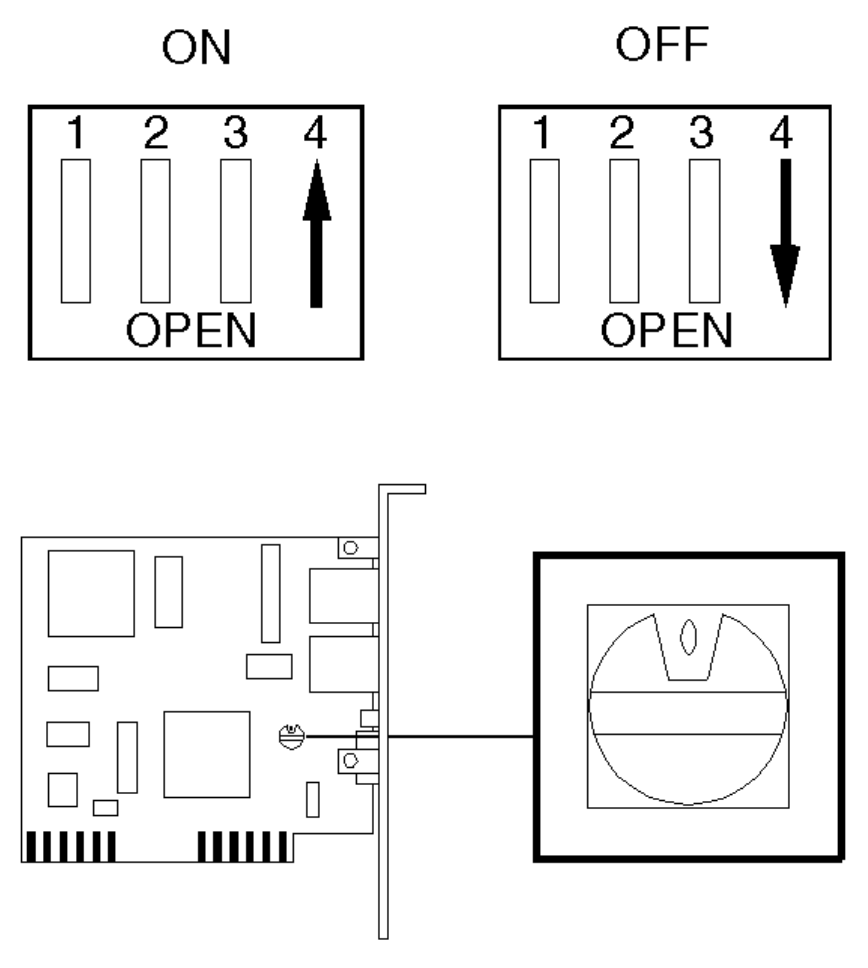
2. On the HP 27245A board with a rotary switch, select the I/O base address and link beat as
shown below:

Switch Position I/O Base Address Link Beat
0 300h (default) ON
1 340h ON
2 320h ON
3 300h ON
4 2C0h ON
5 280h ON
6 240h ON
7 200h ON
8 300h OFF
9 340h OFF
A 320h OFF
B 300h OFF
C 2C0h OFF
D 280h OFF
E 240h OFF
F 200h OFF
HP ETHERTWIST ADAPTER BOARD/16 PLUS (HP 27247B)
The HP 27247B is configured using the HPLANSET utility supplied on the LAN Adapter
Board/16 Plus’s support diskette.
HP 27245A EtherTwist PC Link Phone and LAN Connectors
HP 27247A EtherTwist PC Link 16 Phone and LAN Connectors
CONFIGURATION
Switches
I/O Base Address
The HP 27245A and 27247A boards can be configured to use the following I/O base address:
HP 27245A and HP 27247A I/O Base Address
Link Beat
The link beat is a signal sent over the twisted-pair cable to inform one device of the presence
of another and to verify the integrity of the network link between them.
•If the board will be connected to a Type 10BASE-T network device, enable the link beat
(set switch 4 CLOSED).
•If the board will be connected to a non-10BASE-T network device (such as an HP StarLAN
10 device), disable the link beat (set switch 4 OPEN).
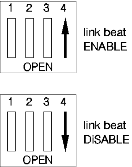
HP 27245A and HP 27247A Link Beat
I/O INTERRUPTS AND MEMORY MAPS
The boards can use the following interrupts:
4 (also used by COM1)
3 (also used by COM2)
7 (also used by LPT1)
5 (also used by LPT2)
Note that the interrupt channel must be selected using the network software supplied with the
server.
CONFIGURATION FILES
The HP 27245A configuration file is: !HWP1820.CFG.
The HP 27247A configuration file is: !HWP1830.CFG.
DRIVERS AND UTILITIES
The board is controlled by network software supplied with the server.
TROUBLESHOOTING TIPS
• Check the board is correctly seated in the computer and correctly configured (no conflicts
with other boards).
• Test the board using the Support Disk supplied with the board.
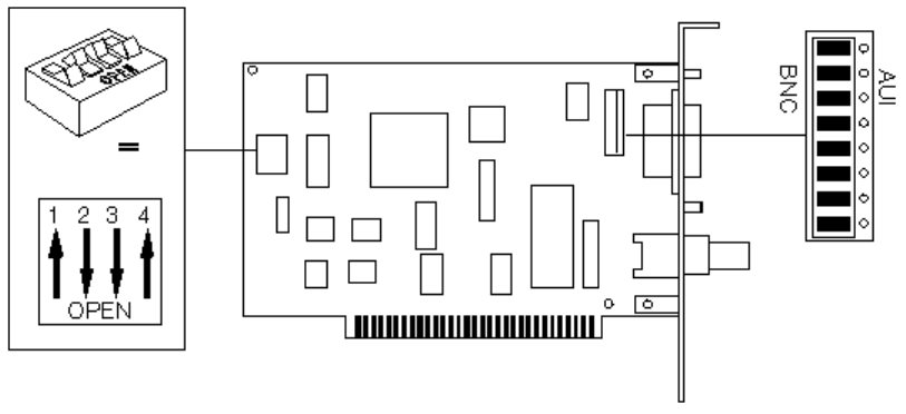
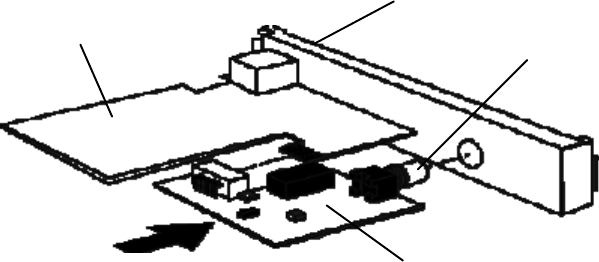
THINLAN PC ADAPTER BOARD (HP 27250A)
Product Information
The HP 27250A ThinLAN board is a “half-length” board that allows the Vectra PC to be
connected to an IEEE 802.3 CSMA/CD 10 Mbit/s network.
The board is equipped with:
• A BNC connector for a ThinLAN Coaxial cable.
• AN AUI (attachment unit interface) for connection to a ThickLAN coaxial, twisted pair or
fiber-optic cable. For this connection, a ThickLAN, twisted pair or fiber-optic MAU
(medium attachment unit) is required.
HP 27250A ThinLAN Switches and Jumpers
CONFIGURATION I/O Base Address Switches
Active Port Jumpers
I/O INTERRUPTS AND MEMORY MAPS
The board can use the following I/O space and interrupts:
Note that the interrupt channel must be selected using the network software supplied with the
server.
4 (also used by COM1)
3 (also used by COM2)
7 (also used by LPT1)
5 (also used by LPT2)
CONFIGURATION FILES
The HP 27250A configuration file is: !HWP1811.CFG.
DRIVERS AND UTILITIES
The 27250A board is controlled by network software supplied with the server.
TROUBLESHOOTING TIPS
• Check the board is correctly seated in the computer and correctly configured (no conflicts
with other boards).
• Test the board using the Support Disk supplied with the board.
ETHERNET 10 BASET BOARD (5063-8790) AND BNC COAX ADAPTER
(D3979A)
The Ethernet 10 BaseT board (5063-8790) has a RJ-45 connection. For a BNC coax
connection, use the BNC Coax Adapter (D3979A).
Ethernet 10 BaseT Board
RJ-45 Connection
BNX Coax Connection
BNC Coax Adapter
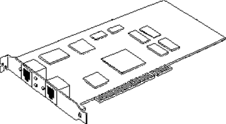
10/100 VG SELECTABLE PCI LAN ADAPTER (J2585A)
Product Information
The 10/100 VG Selectable LAN adapter supports two standards:
• 100-Mbits/s mode, for attachment to IEEE 802.12/100VG-AnyLAN network
• 10-Mbits/s mode, for attachment to IEEE 802.3/Ethernet 10-BaseT network.
For a BNC coax connection, use the BNC Coax Adapter (D2764A).
INDICATOR LIGHTS
The 10/100 VG Selectable LAN adapter features four indicator lights on the back panel:
• Activity light, showing network activity
• Link status light
• 10-Mbits/s light
• 100-Mbits/s light.

Use the following tables to interpret the indicator lights:
10-Mbits/s Operation
Link Status
Light 10-Mbits/s
Light 100-
Mbits/s
Light Explanation
ON ON OFF Normal operation
OFF OFF ON Either:
Cable is not connected to an active
10BaseT network.
Cable is defective.
LAN Adapter is defective.
100-Mbits/s Operation
Link Status
Light 10-Mbits/s
Light 100-
Mbits/s
Light Explanation
ON OFF ON Normal operation
OFF OFF ON Either:
Cable is not connected to an active
100VG network.
Cable is defective.
LAN Adapter is defective.
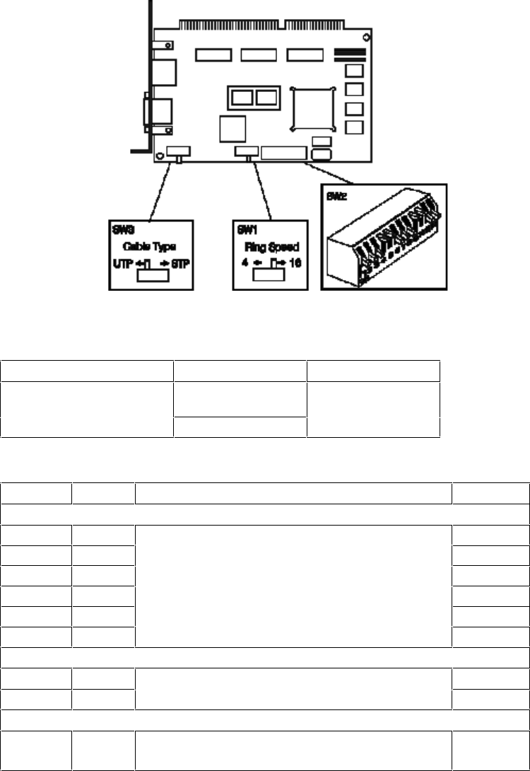
HP TOKEN-RING ADAPTER (D2378A)
Discontinued March 1994
The D2378A Token-Ring Adapter has three switch blocks, “SW1”, “SW2”, and “SW3”.
Token-Ring ISA 16/4 Adapter Board (D2378A) Switches
Ring Speed Selection Switch SW1
Function Position Default
Ring Speed (in millions of
bits per second) 44
16
Switch Block SW2
Switch Name Function Default
Switches that are not used
1 EN Leave at default setting. ON
217 ON
316 ON
4 15 OFF
5 14 OFF
613 ON
IRQ (interrupt level) Selection
7I1Default: IRQ9. See table below for other settings. ON
8I0 ON
I/O Address Selection
9
10
A1
A0
Default: A20-A23 and A30-A3F. See table
opposite for other settings. OFF
OFF
DMA Channel Selection
11
12
D1
D0
Default: DMA 5. See table opposite for other
settings. ON
ON
IRQ Selection (SW2)
IRQ Switch 7 Switch 8
IRQ3 ON OFF
IRQ9 ON ON
IRQ10* OFF ON
IRQ11 OFF OFF
*IRQ10 and IRQ11: only available in 16-bit slots
I/O Address Selection (SW2)
Address (hex)* Switch 9 Switch 10
A20-A23 and A30-A3F OFF OFF
A24-A27 and A40-A4F ON OFF
A50-A53 and A60-A6F OFF ON
A54-A57 and A70-A7F ON ON
*On standard ISA PCs, address Axx is interpreted as address 2xx
DMA Channel Selection (SW2)
DMA Switch 11 Switch 12
DMA 5 ON ON
DMA 6 ON OFF
DMA 7 OFF ON
Programmed I/O OFF OFF
*If the board is in an 8-bit slot, programmed I/O is used automatically

MODEMS (HP 24550A/1A)
Discontinued January 1991
The HP 24550A internal 1200 baud modem has a four-way switch block. The HP 24551A
internal 2400 baud modem has a six-way switch block. The function of the first four switches is
the same on both modems. The default setting has all the switches open.
Switch Block Settings
Switch State Function Default
1OPEN DTR not forced. DTR only in receipt of signal from
the PC. OPEN
CLOSED DTR is forced. PC assumes DTR is on at all times.
2OPEN The modem answers calls after 1 ring. OPEN
CLOSED The modem does not answer calls.
Comm Port Selection
3 OPEN Switch 3 and 4 are used together to set the comm.
port. Default is COM 2. See table below for other
settings.
OPEN
4
HP 24551A Only
5OPEN DTR not forced. DTR only in receipt of signal from
the PC. OPEN
CLOSED DTR is forced. PC assumes DTR is on at all times.
6OPEN Not used. Must be left open for the modem to
operate. OPEN
Communications Port Selection
COM Switch 3 Switch 4
COM 1 CLOSED OPEN
COM 2 OPEN OPEN
COM 3 CLOSED CLOSED
COM 4 OPEN CLOSED

Speciications
Feature HP 24550A (1200 baud) HP 24551A (2400 baud)
Data Rates (Baud) 110, 300, & 1200 110, 300, 1200, & 2400
Data Formats 8-bit, no parity;
7-bit, even/odd/mark/space parity
Modem Compatibility
300 baud Bell 103, 113, & 212-A Bell 103, 113
1200 baud Bell 212-A CCITT V.22 & Bell 212-A
2400 baud N/A CCITT V.22
Receiver Sensitivity -45 dbm
Transmit Level -10 dbm -9 dbm
Tone Dial Level 0 dbm -1 dbm
Line Impedance 600 ohms
Ringer Equivalence 0.4B 0.1B
Modulation
300 baud Frequency Shift Keyed (FSK)
1200 baud Differential Phase Shift Keyed (DPSK)
2400 baud N/A Quadrature Amplitude
Keying (16 point phase
shift keyed)

REPLACEABLE PARTS FOR DATA COMMUNICATIONS AND LAN ADAPTER
BOARDS
Description Replacement
Part Number
Exchange
Part Number
Terminal Multiplexor (D2040A)
Serial Parallel Board (24540B) 24540-60031
-
Dual Serial Board (24541B) 24541-60031
-
Ethertwist PC Link Adapter (27245A) 24745-60001
Ethertwist Adapter/16 (27247A/B) 27247-60001
27247-69001
Token-Ring Adapter (D2378A) 2378-60001
2378-69001
HP ThinLAN board (27250A) 27250-60001
Modem 1200 baud (24550A) -
Modem 2400 baud (24551A) -
24551-69002
BNC Coax Adapter (D3979A) D3979-63001
-

7 HP MULTIMEDIA PRODUCTS
This chapter provides information about the following HP Multimedia products, including
Replacement Part Numbers.
• HP Sound DSP 16 (D2941A)
• HP Integrated-Office (D2887A)
Information about CD-ROM drives can be found in Chapter 5.
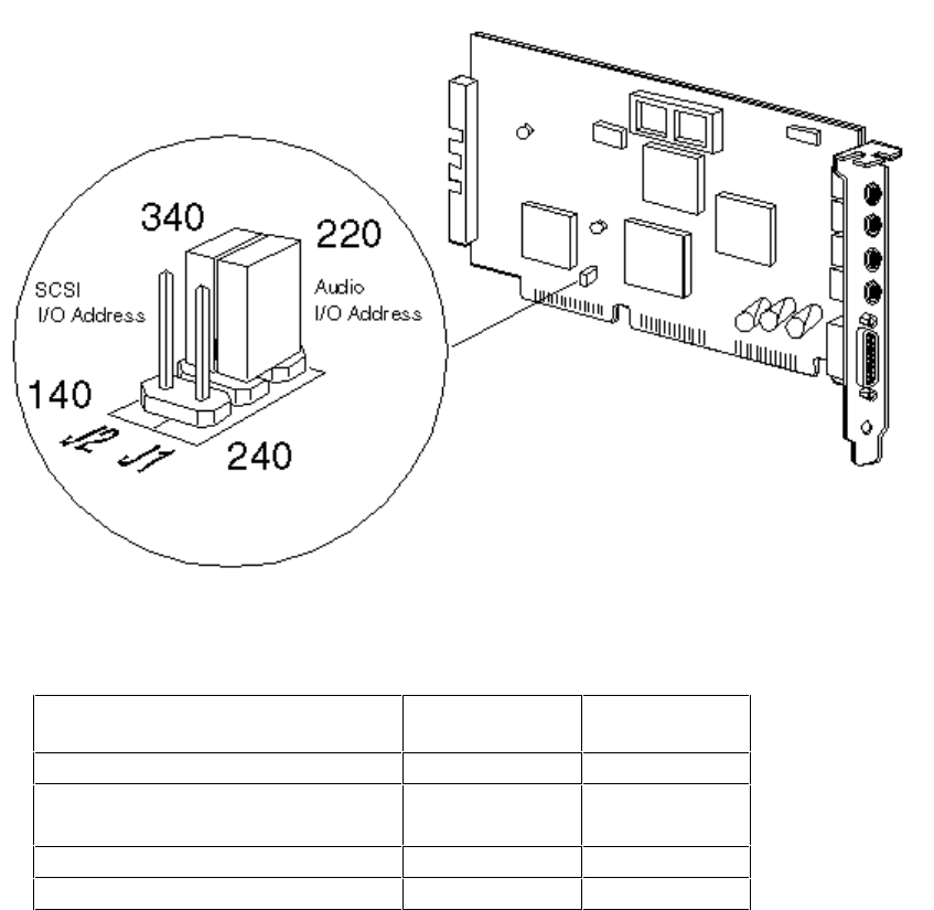
HP SOUND DSP 16 SCSI-1 (D2941A)
There are two jumpers on the HP Sound DSP 16 board to select alternative I/O addresses for
the SCSI interface for the CD-ROM and the audio hardware.
The SCSI jumper is set to 340 h, which is the I/O address used by most SCSI adapter boards.
This can be changed to select an I/O address of 140 h.
The audio jumper is set to 220 h, which is the address used by most audio products (some
sound software will not recognize another address). This can be changed to select an I/O
address of 240 h.
Replaceable Parts
Description Replacement
Part Number Exchange
Part Number
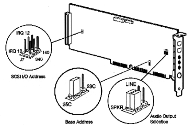
HP INTEGRATED-OFFICE (D2887A)
The SCSI interface I/O address and IRQ are configured by software. Certain operating
systems, which may be delivered on CD-ROM (OS/2 or Windows NT, for example), may
require these values to be forced by hardware using the SCSI I/O address jumpers shown
below. Otherwise, these jumpers should be left in the factory preset open position.
The HP Integrated-Office has jumpers to control the signal to the Line OUT connector. When in
SPKR position, the output is amplified using the on-board amplifier. In this position the volume
level may be controlled by software. This position may be used for small non-amplified
speakers or headphones. In LINE position, the output is not amplified. This position may be
used with an external amplifier, and the software volume control has no effect.
The board is delivered with the I/O base address set to 25Ch. You should not have to change
this address unless the selected base address conflicts with another accessory.
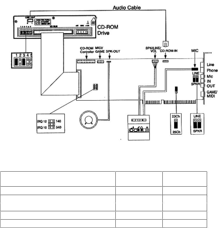
INTERNAL CONNECTIONS
This figure shows where the connections are made on the HP Integrated-Office board.
Replaceable Parts
Description Replacement
Part Number
Exchange
Part Number
-
-
-
-
-